Antigravity Batteries rock

The new code I’ve entered is for a MUCH smaller battery, this time a 50Ah AGM battery. The voltage at the battery is always well above 13V.

Ross-Tech replied to Volvofan stating they didn’t think the Gateway wouldn’t support a lithium ion battery due to the car being seven years old. But gave no logic behind that very unscientific statement. I’ve asked him to elaborate as to what “wouldn’t support” means from an electrical standpoint.

Thinking last night, I have a feeling it may have to do with the alternator charging under braking (or charging period) and then when you accelerate, the increased rate of discharge from the battery may be causing issues, somewhere in that quick transition. It’s not a voltage dip, that’s for sure but the car does go into some sort of protection mode.

The other line of thought is it’s the AG battery itself which is shutting down when it sees more than 14.7V from the alternator.

There are no battery-related errors when you pull up the VCDS and scan for codes. The codes only seem to exist in other unrelated modules.

I’ve not tried to find the battery menu in the green screen as I figured it’d be easier to accomplish this with the VCDS. I’ll look into it and see what options are in there.

I still find it odd an add-on CarPlay unit causes the same errors if the “dual clutch support” box isn’t checked in the unit’s setup menu. Maybe the circuitry inside the AG has some sort of firmware that doesn’t play nice the CanBus in a similar fashion.

When I was having it on my 2013 S5 I got a couple of spikes all the way to 15volts. It would be a fairly violent safe mode kicking in. The transmission would kick into a neutral, without an indication of neutral, engine would go to idle, then about 5~10sec later it would recover. I would get a Transmission warning in the DIS but when I’d scan it at home with Vagcom there would be not transmission or engine faults. Still running the OEM battery in the S5 but would like to go with the AG in both the S5 & RS5. S5 Alternator 150amp Valeo, RS5 190amp Hitachi, same battery and electrical module part #'s.
From the B8.5 N. America press release: “The powerful RS 5 features an optimized engine and drivetrain, on-demand oil pump, and
energy-recovery system that conserve energy during coasting and braking.” And read the Recuperation part of this Audi brochure.

As it cranks up effortlessly with the Antigravity battery, maybe the battery settings are a bit too good (=powerful) for what is needed. Can you limit/lower the output voltage slightly from the battery via an update over the bluetooth for cars with recuperation. Or change the fast charge setting so it can “trap” the spike.

Or, since AGMs are allegedly capable of higher recuperation than regular lead acid batteries, try an adaptation for the latter?

I tried the AGM on my S5 but I was using a small AG battery, half the amps of a OEM battery. Still cranked the car up fine, no difference. I’m sure the Reserve capacity if I let it sit off a trickle charger would have shown. AGM setting didn’t help in my case but we’ll see with a bigger AG battery that I’m going to install. I want to get this figured out here or on my S5 before I get the RS5 back on the road. Really can’t pass up on shedding almost 50lbs from the car.

Exactly, I am also in the market for one.

I meant use a standard lead acid battery setting (“conv” in the list above?), with the li-ion Antigravity battery.

The reason being I am assuming the AGM setting would regenerate more aggressively as the AGM batteries are meant to allow for it. The idea that they can manage cars with start-stop functionality: in stop and go city traffic they need to recharge effectively at coasting and stopping so they can crank up repeatedly.


flooded lead acid

vcds

vcds guide

Ok…have a better understanding of the issue with RS Nav and dual clutch gearboxes…apparently it’s a handshake issue where instead of just “listening” the RS Nav unit was trying to talk to the CanBus. So that’s a no go in correlating anything with the AG batteries as the only electrical hookup is the positive/negative and there’s no other interface into the car’s wiring harness to transmit actual data.

I went out and did a bunch of logging with the new code I’m using and so far no issues. Volvofan is on to something though and if he doesn’t post here, I’ll post it up.

Right now he’s using a 1.5V battery and a circuit to trick the BMS into seeing a higher voltage than what really exists. Our goal is to keep voltage below 14.4v. The other thing that works is to just disconnect the BMS in the trunk altogether. There’s a two wire plug. Pull it and you’ll get a constant voltage. Don’t know what the long-term effects of that are.

As soon as I’m done with my maintenance marathon on my car, I’ll graph out my logs and post them. You can clearly see the alternator is producing recharging voltage levels on deceleration.

Here’s volvofan’s post…
" Okay, getting closer to a solution. First of all, I’m going to take the info from my post immediately above and edit into the first post of the thread, so that folks don’t have to dig when referencing this.

Second, I am testing a couple different methods to spoof the Battery Monitoring & Control Module (BMCM, aka J367). I’ve had some success in “static” (aka car idling in my driveway) testing, but haven’t done any “dynamic” testing yet. Will report back. Once again, I’ll update the first post with these results in more detail, but I see the following methods as viable options for addressing this issue:

  1. CODING. This should be your first stop. Try re-coding the BMS with a battery part number that’s closer to the amp-hours of your AG battery (or other LiFePo4 replacement). Make sure you use a new serial number (second part of the BEM). I do NOT recommend trying the EFB or AGM part numbers… even though those types of batteries supposedly are closer to the charging profile of what the LiFePo4 batteries want, I found that I got MUCH worse overvoltage spikes when running that part number. Stick to the conventional ones. PROS: Free (if you have the necessary hardware) and minimally-invasive. CONS: You need to have the necessary hardware (VCDS, OBDeleven, etc), doesn’t seem to work for everyone.

  2. DISCONNECT BMCM. Unplug the two-wire connector at the negative battery terminal. This places the car into a “fallback” mode. Alternator puts out no more than 14.3V, whereas I was seeing up to 15V at idle with it connected. I haven’t done any driving tests to see if this has any other adverse effects. PROS: Free. CONS: You are defeating some of the functionality of the vehicle; this may have other side-effects of which I am not yet aware.

  3. DROP OUTPUT VOLTAGE OF ALTERNATOR. Install a high-amperage diode inline with what goes from the alternator to either the jumper block in the cowling under the hood, or to the main fuse block on the positive battery terminal. Not sure which would be better, as I haven’t tested this yet. The part is on the way, though, and I intend to. PROS: A “hardware” solution for limiting alternator voltage doesn’t rely on software reaction time. CONS: Costs about $25 plus installation time, may have other side effects, inefficient (wasting excess voltage as heat), and reduces alternator output voltage ALL the time (even at lower RPMs when you may not want voltage to be lower).

  4. SPOOF BMCM WITH BATTERY AND DIODE/POT. Put a 1.5V (AA, C, D, doesn’t matter) battery in series with the voltage-sensing lead from the positive terminal to the BMCM. Add either a diode (or diodes) to drop voltage “boost” to the level that gives you the best performance), or a voltage divider/resistor of some sort. This tells the BMCM that the battery’s voltage is higher than it actually is, as I theorized above. I tested this, and it DOES work. Adding about 0.6-1v seems to get the BMCM to tell the J533 module to tell the alternator to chillax and dial back its output voltage. It was a crude test, and I didn’t do any driving to see if this solves the problem under all conditions, but it’s promising. PROS: Relatively inexpensive, simple, retains functionality of J367 module to adjust alternator load to varying conditions without overcharging AG battery. CONS: May take some trial-and-error to tweak/tune, and the 1.5V battery will need to be changed out periodically.

  5. SPOOF BMCM WITH VOLTAGE BOOSTER AND OP-AMP. Same effect as described above… lie to the BMCM. Haven’t tested this yet, but the components come today. PROS: retains functionality of J367 module to adjust load to varying conditions without overcharging, most customizable solution (can use potentiometers to dial in precise voltage gain), no current draw when off, no 1.5V battery to change. CONS: Most complex solution, requires some rudimentary soldering and fabrication skills, costs about $30 in components (voltage booster, op-amp, relay, taps, wiring, board, etc.)

-Jon"

So we’ve done more experimentation and Jon’s built an electronic interface that tricks the battery management system into seeing more voltage than is actually being produced. I’ll be building one myself to test.

In the meantime, I went and unplugged my battery management system from the battery. Takes two seconds, small, two wire plug on the battery’s negative terminal.

VIOLA! No more over voltage on deceleration. I typically see between 13.6 and 14.3. Battery charges as normal and there do not seem to be any downsides as far as I can tell. I did a 50 mile trip in full hooligan mode and no issues. I then ran my typical errand loop, multiple stops at various stores and again, zero issues. Car sits for a week and the battery voltage levels are where they should be. So it seems we’re good to go with that method.

I still want to try out Jon’s contraption as there will be a “soft” code if you were to do a scan with the VCDS and the BMS disconnected. NO DASH LIGHTS with this method however. Have a friend who’s testing on an RS3 and this seems to work for him just fine. Another client with a TTRS has had zero issues with his Antigravity. Go figure.

I’ll post up more info from Jon today, including the schematic for building his spoofer.

1 Like

Still running my BMS unplugged with zero issues.

This is where Jon is in his endeavors…

Okay, getting closer to a solution. First of all, I’m going to take the info from my post immediately above and edit into the first post of the thread, so that folks don’t have to dig when referencing this.

Second, I am testing a couple different methods to spoof the Battery Monitoring & Control Module (BMCM, aka J367). I’ve had some success in “static” (aka car idling in my driveway) testing, but haven’t done any “dynamic” testing yet. Will report back. Once again, I’ll update the first post with these results in more detail, but I see the following methods as viable options for addressing this issue:

  1. CODING. This should be your first stop. Try re-coding the BMS with a battery part number that’s closer to the amp-hours of your AG battery (or other LiFePo4 replacement). Make sure you use a new serial number (second part of the BEM). I do NOT recommend trying the EFB or AGM part numbers… even though those types of batteries supposedly are closer to the charging profile of what the LiFePo4 batteries want, I found that I got MUCH worse overvoltage spikes when running that part number. Stick to the conventional ones. PROS: Free (if you have the necessary hardware) and minimally-invasive. CONS: You need to have the necessary hardware (VCDS, OBDeleven, etc), doesn’t seem to work for everyone.

  2. DISCONNECT BMCM. Unplug the two-wire connector at the negative battery terminal. This places the car into a “fallback” mode. Alternator puts out no more than 14.3V, whereas I was seeing up to 15V at idle with it connected. I haven’t done any driving tests to see if this has any other adverse effects. PROS: Free. Easy. CONS: You are defeating some of the functionality of the vehicle; this may have other side-effects of which I am not yet aware.

  3. DROP OUTPUT VOLTAGE OF ALTERNATOR. Install a high-amperage diode inline with what goes from the alternator to either the jumper block in the cowling under the hood, or to the main fuse block on the positive battery terminal. Not sure which would be better, as I haven’t tested this yet. The part is on the way, though, and I intend to. PROS: A “hardware” solution for limiting alternator voltage doesn’t rely on software reaction time. CONS: Costs about $25 plus installation time, may have other side effects, inefficient (wasting excess voltage as heat), and reduces alternator output voltage ALL the time (even at lower RPMs when you may not want voltage to be lower).

  4. SPOOF BMCM WITH BATTERY AND DIODE(S). Put a 1.5V (AA, C, D, doesn’t matter) battery in series with the voltage-sensing lead from the positive terminal to the BMCM. Add a diode (or diodes) to drop voltage “boost” to the level that gives you the best performance. This tells the BMCM that the battery’s voltage is higher than it actually is, as I theorized above. I tested this, and it DOES work. Adding about 0.6-1v seems to get the BMCM to tell the J533 module to tell the alternator to chillax and dial back its output voltage. It was a crude test, and I didn’t do any driving to see if this solves the problem under all conditions, but it’s promising. PROS: Relatively inexpensive, simple, retains functionality of J367 module to adjust alternator load to varying conditions without overcharging AG battery. CONS: May take some trial-and-error to tweak/tune, and the 1.5V battery will need to be changed out periodically.

  5. SPOOF BMCM WITH ISOLATED DC-DC CONVERTER & DIODES. Same effect as described above… lie to the BMCM. Basically replace the 1.5V battery with an isolated DC-DC converter so it never has to be changed or charged. Found one that steps down to 3.3V, then we’ll have to get down to the desired “boost” voltage by adding a few diodes to drop the voltage to whatever works best (again, shooting for somewhere between 0.6 and 1v). Haven’t tested this yet, but the components will be here early next week. PROS: retains functionality of J367 module to adjust load to varying conditions without overcharging, no current draw when off, no 1.5V battery to change. CONS: Most complex solution, requires some rudimentary soldering and fabrication skills, costs about $30 in components (DC-DC converter, diodes, relay, enclosure, wiring, board, etc.)

-Jon

Latest updates-

Simply disconnecting the BMCM has been effective. Voltage (according to the battery tracker) recharges to 14v shortly after startup, and no features are disabled (i.e. seat heaters, high beams, rear defrosters, etc.). I’ve seen no voltage spikes or adverse effects on any other vehicle systems, though I know this is throwing a “soft code” that’ll show up on a VCDS auto-scan. Also, since this is only a viable solution for the Audi cars that use this particular method of energy management (many other models have a more complex external regulator or an integrated electrical systems control module… neither of which should simply be unplugged!), I will continue to puruse the “spoofing” route.

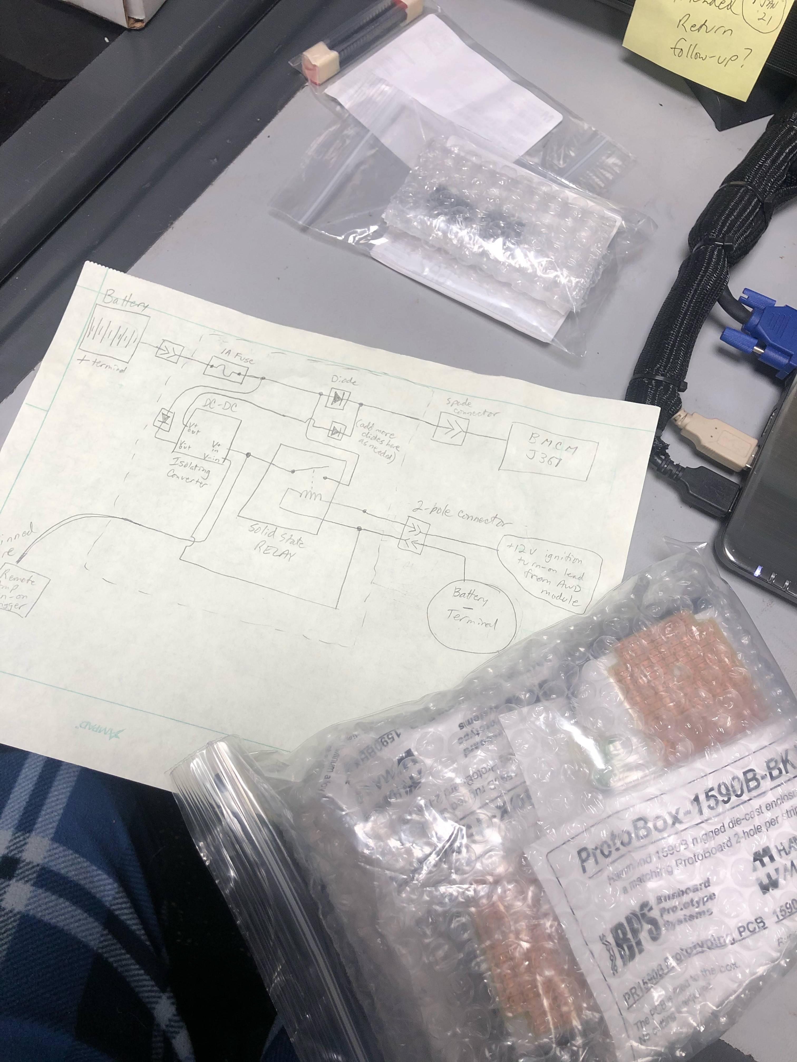
Here are a couple photos (and the schematic) of the prototype I’ve created to inject a little extra voltage into the BMCM’s sensing lead without throwing off any other vehicle systems. It’s simpler than it looks… cut the wire going from the battery to the BMCM, and that’s two of your connections. One more goes to the battery terminal itself to provide ground, another gets “switched” power when the ignition is on via a tap off of the wiring harness to the AWD module that also happens to sit in the trunk (some models have a whole “ignition hot” fuse block in the trunk but not our 5 series, I believe… or at least not my RS5. I have a fifth wire that’s also turning on my subwoofer amplifier, but that’s optional.

HOW IT WORKS: When the ignition is off, the module is “passive”. Voltage flows from the battery positive terminal (through a low-amp fuse and a small Schottky diode to keep the module isolated in case I messed something up) and on to the BMCM as it usually does, reflecting accurate battery voltage within a tenth of a volt (small drop due to the diode). When the ignition is on, the +12V tapped from the AWD module’s harness engages a solid-state relay (I picked a SSR to ensure only minimal drain on the stock system so it won’t even know it’s there). That relay then provides a 12v signal to an ISOLATED (it MUST be isolated) DC-DC converter that steps the voltage down to 3.3v. It also sends a 12v signal to turn on my amp ;). Then, I run that 3.3v IN SERIES WITH the battery wire going to the BMCM so that the voltage generated gets ADDED to the battery’s voltage. Using a few diodes in line with that wire (each diode has a voltage drop associated with it, but has low impedance so once again the car shouldn’t know any better), I can drop the added voltage to whatever level we desire. Probably going to be shooting to add around 0.7 volts, as I’ve seen this alternator put out up to 15v. Ultimately, I’ll be looking for whatever amount of diodes causes the car to charge the battery to about 14.1 or 14.2 V WITHOUT any associated voltage spikes.

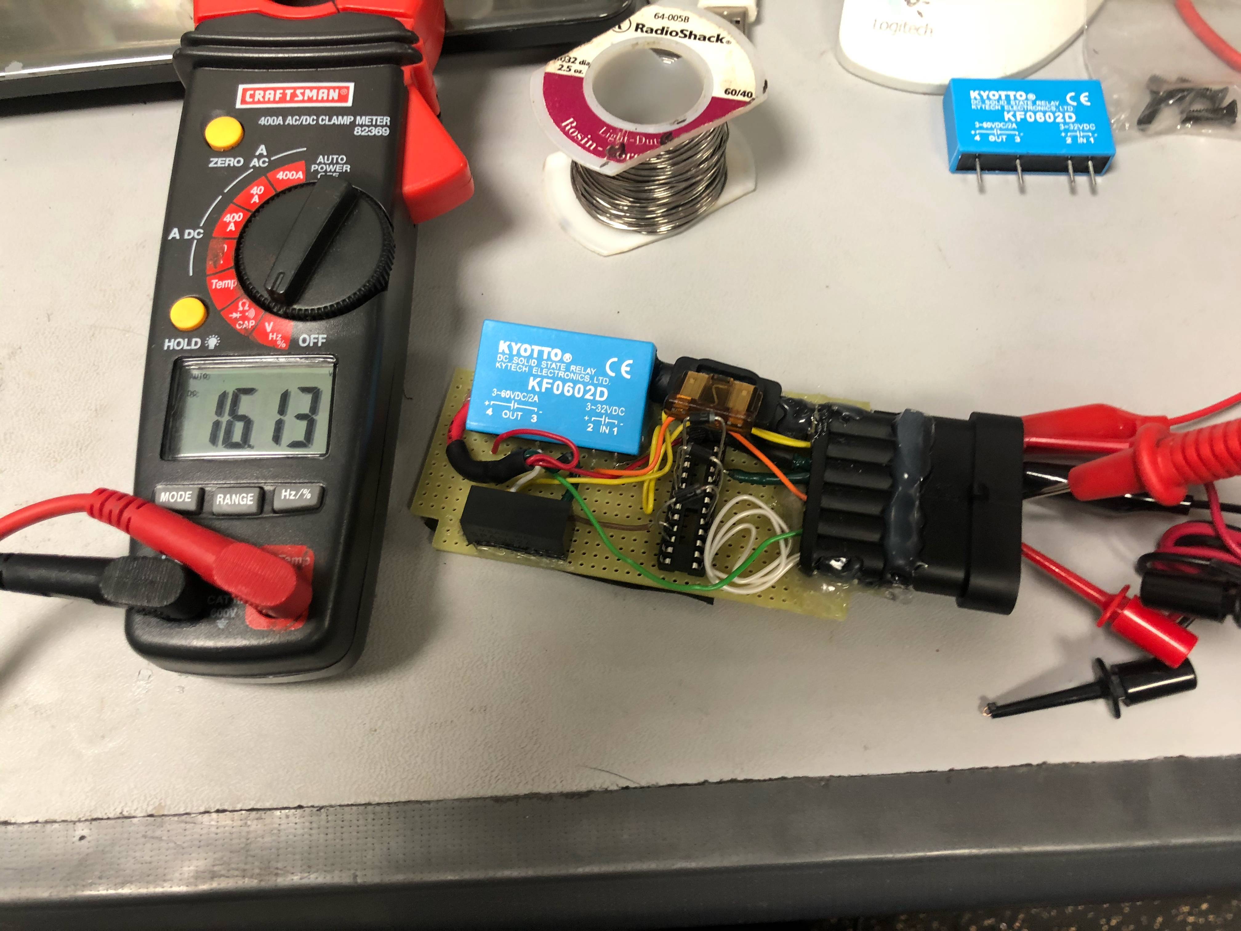
In the photo below, I have three “regular” diodes and one Schottky diode in series. My bench power supply puts out about 13.9V and I’m seeing about 16.1V on my multimeter… a boost of around 2.2v. Before I install it in the car, I’ll probably end up adding four more “regular” diodes (the IC socket has its pins soldered together in pairs, allowing me to use it like a breadboard to quickly test different combinations without soldering).

\ 16x16

\ 16x16

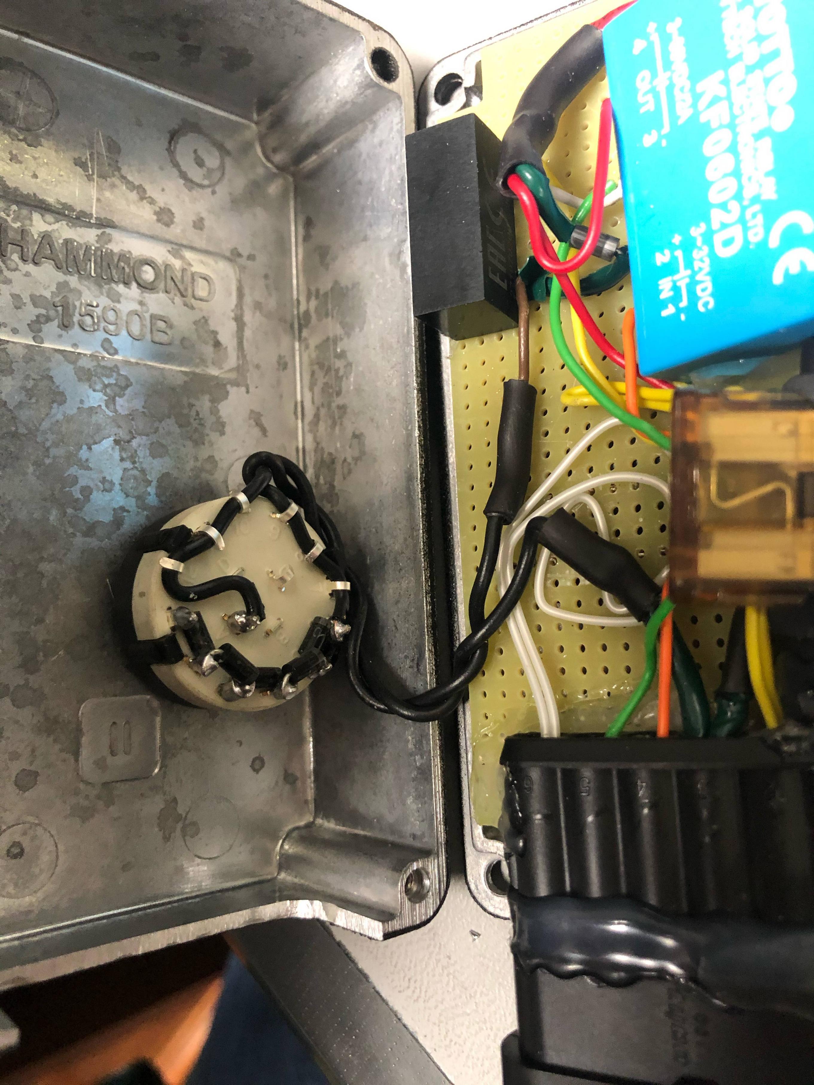
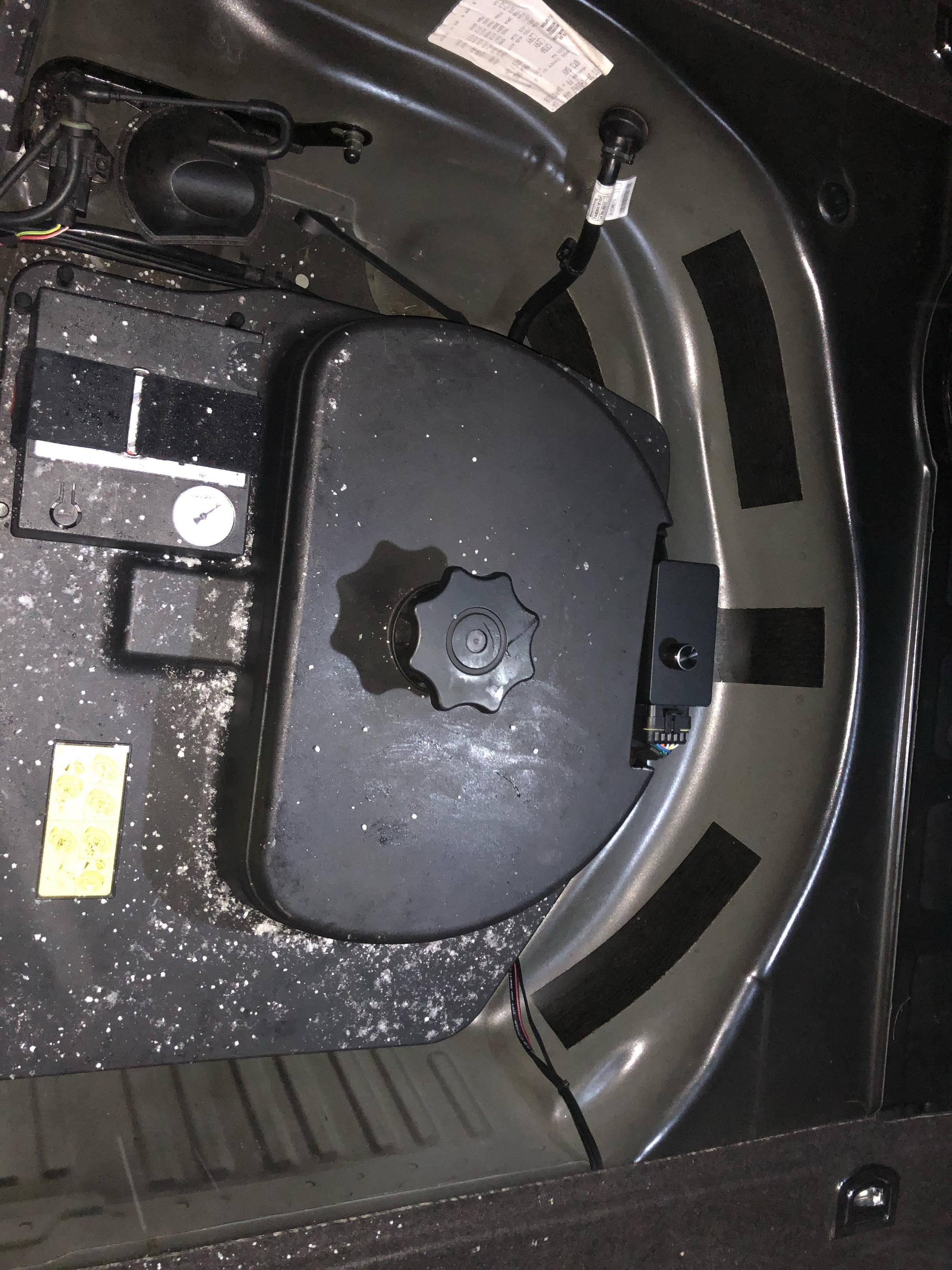
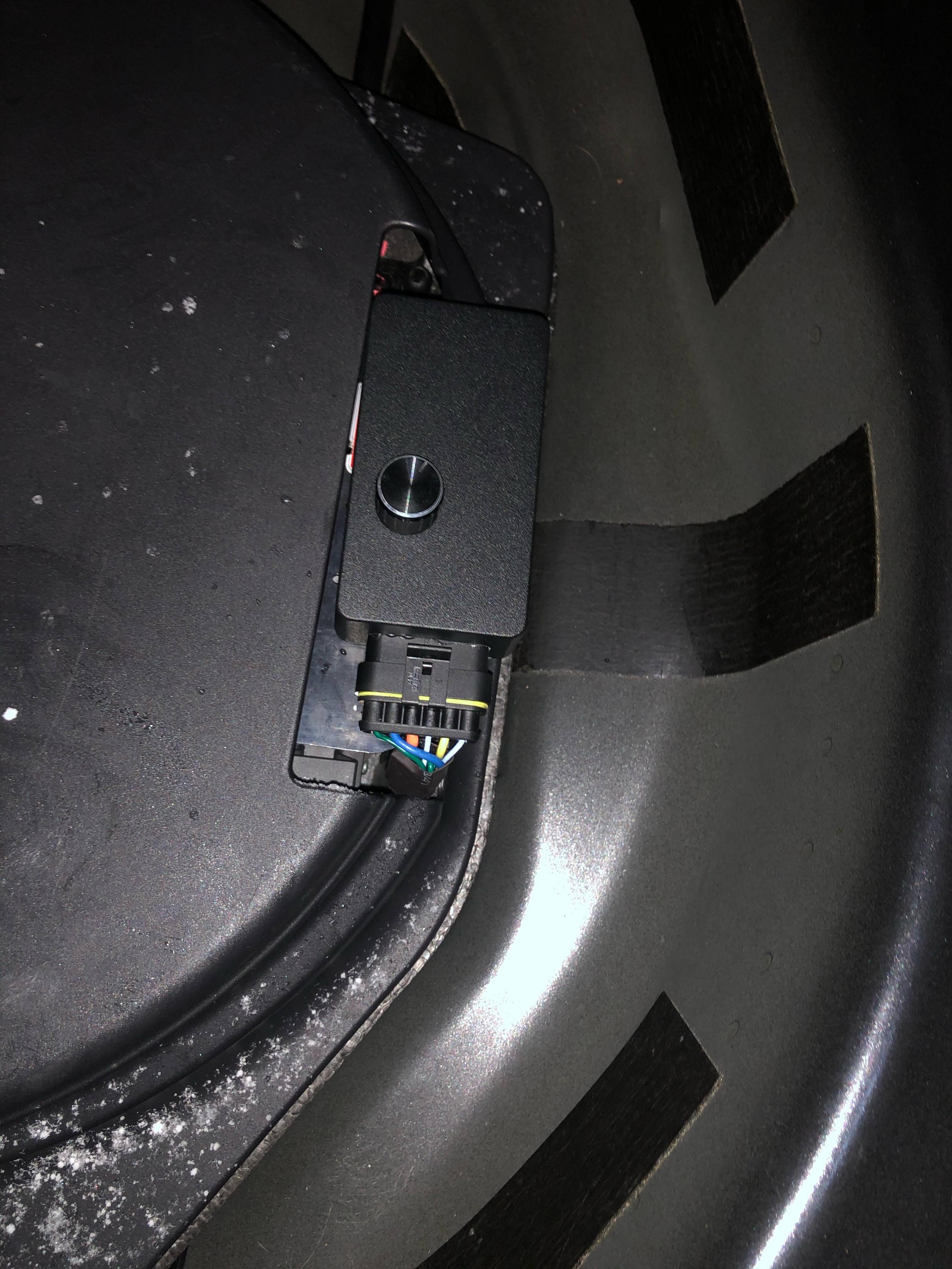
Update - the IC socket sucks for holding diodes. I honed in on the approximate number of regular and Schottky variants I needed, and ended up soldering them all into a multi-position rotary switch, so I can adjust the outputted “boost” voltage on the fly. Here is a schematic that is more reflective of my final prototype, with some further improvements to ensure voltage remains isolated and the car is protected against backfed current while increasing the “fine-tunability” of the boost voltage. Also, some more photos of the finished product.

\ 16x16

\ 16x16

\ 16x16

\ 16x16

\ 16x16

With all that above, it appears either getting a 60Ah version of the battery or unplugging the BCM works as well…no reported issues so far with a 60Ah model. James pointed out a battery is nothing but a large capacitor and the larger Ah batteries may have more ability to absorb voltage spikes.

I do have a 60ah AG that I had sitting aside for the RS5, I’ll stick it in the S5 and drive it for a while to see if it solves the problem. They list the YTX12-24 I was using as a 30ah battery.

Awesome, that’d be great!

Jon, I’m sure you’ve looked through Vagcom a bit, here are a couple of screen shots of my CAN Gateway module Long coding choices. Recuperaton? Battery Data Module? These are on my S5 not the RS5, I didn’t scan the RS5 but I’m sure they are the same, I was coding something else and came across these

I’ll have to take a look and see if I have the same. If there were some way to limit the voltage in recuperation mode, that’d be the ticket.

BMW’s are so bad these days they ONLY recharge on deceleration. Track day guys sometimes end up with a dead battery as they’re never in lift throttle, LOL.