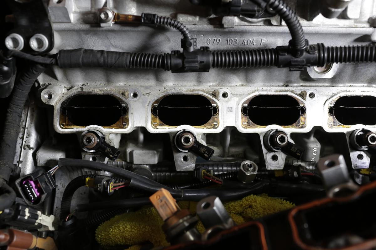
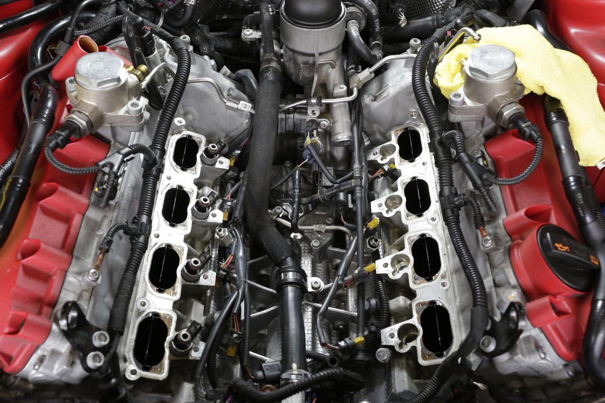
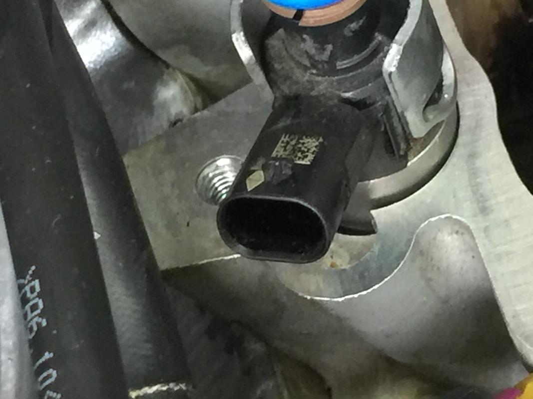
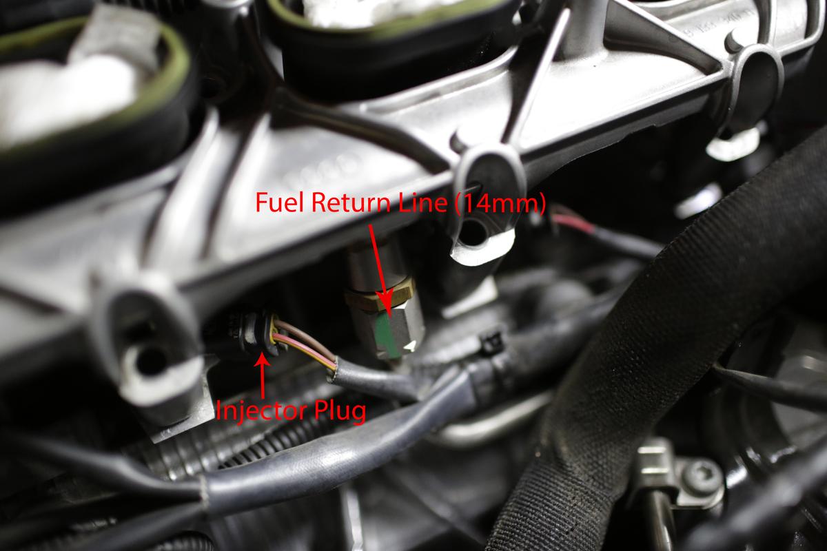
Closeup of one bank after the LIM was removed. The injectors are still in there but they did come up slightly, enough that I knew I’d need to replace the seals.
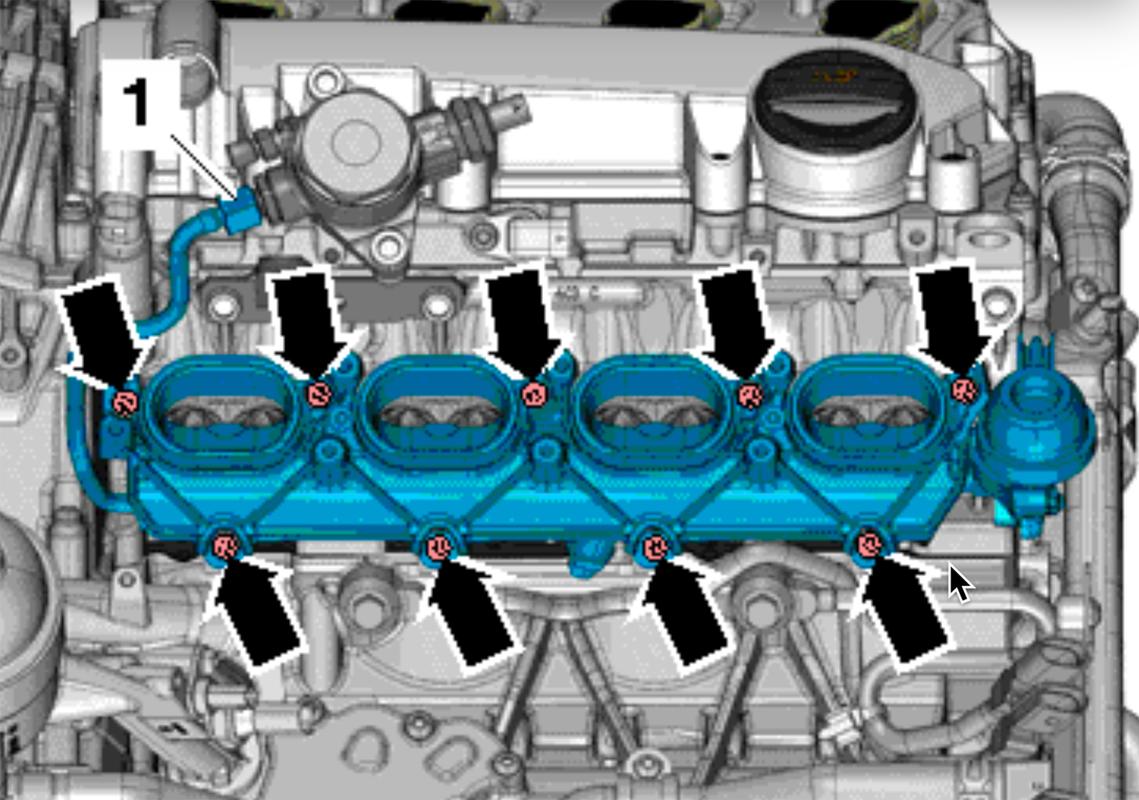
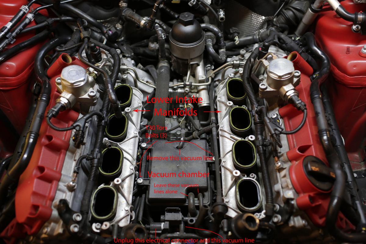
Overall of the engine valley with the LIM removed.
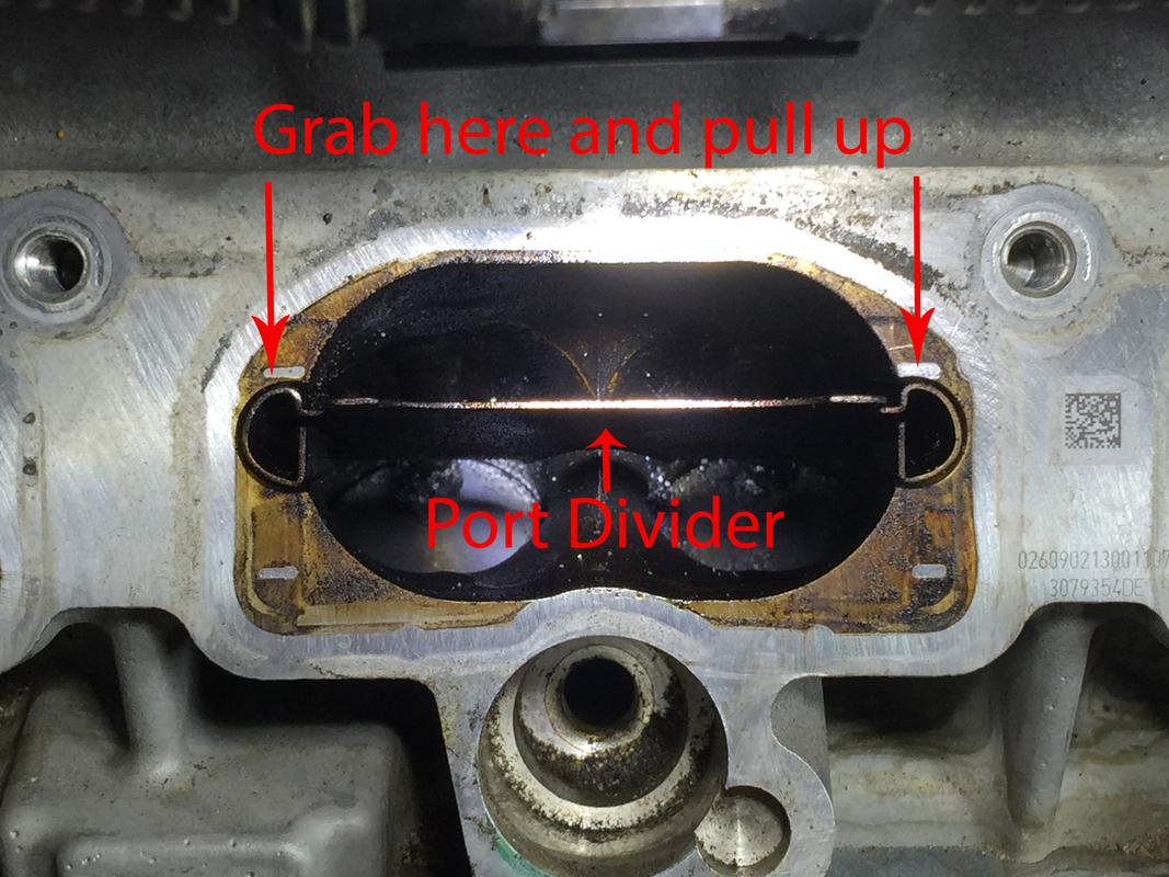
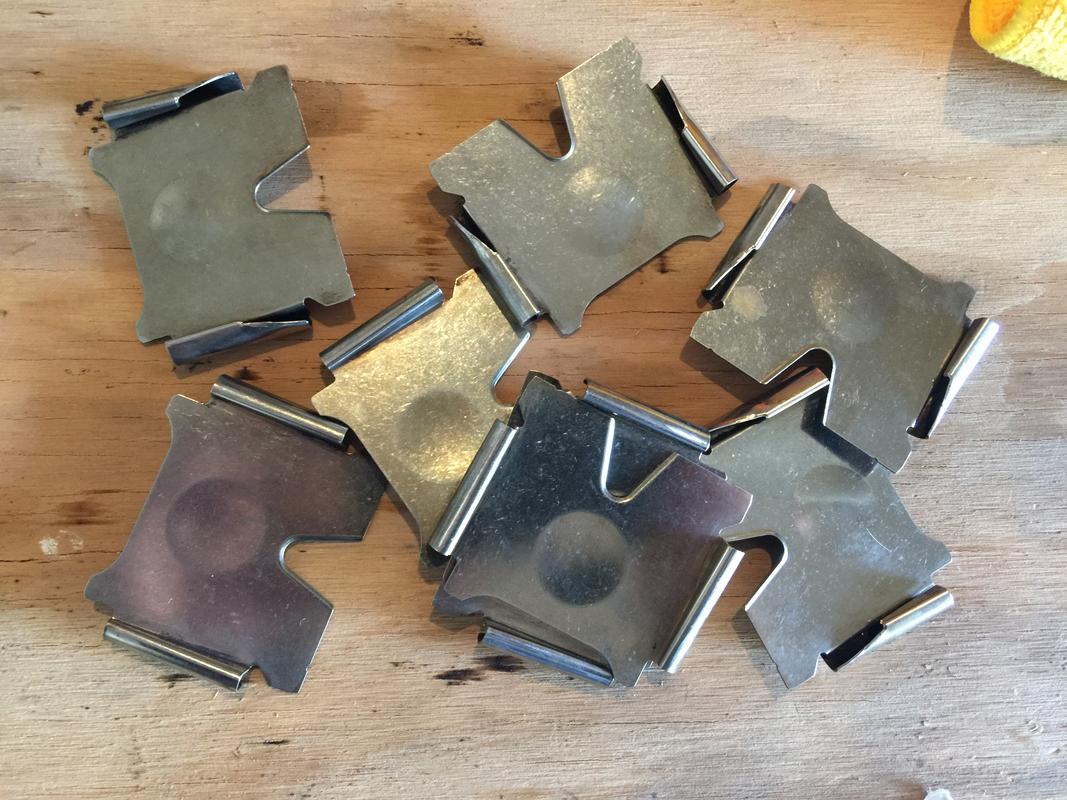
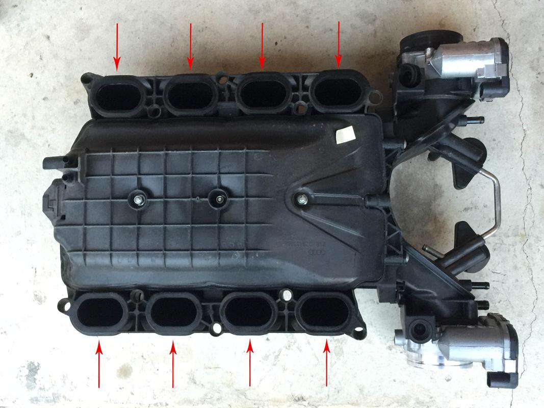
The next step is to remove all eight of the port dividers in the intake runner. Just use a pair of thin or needle nose pliers. Grab each side by the “D” shape, wiggling the divider and going from one side to the other as you pull up. Pull all of them and soak in some sort of carb or carbon cleaner. You’ll clean them off and reuse them. The protruding dimple faces down when you go to reinsert them back into the intake runners…
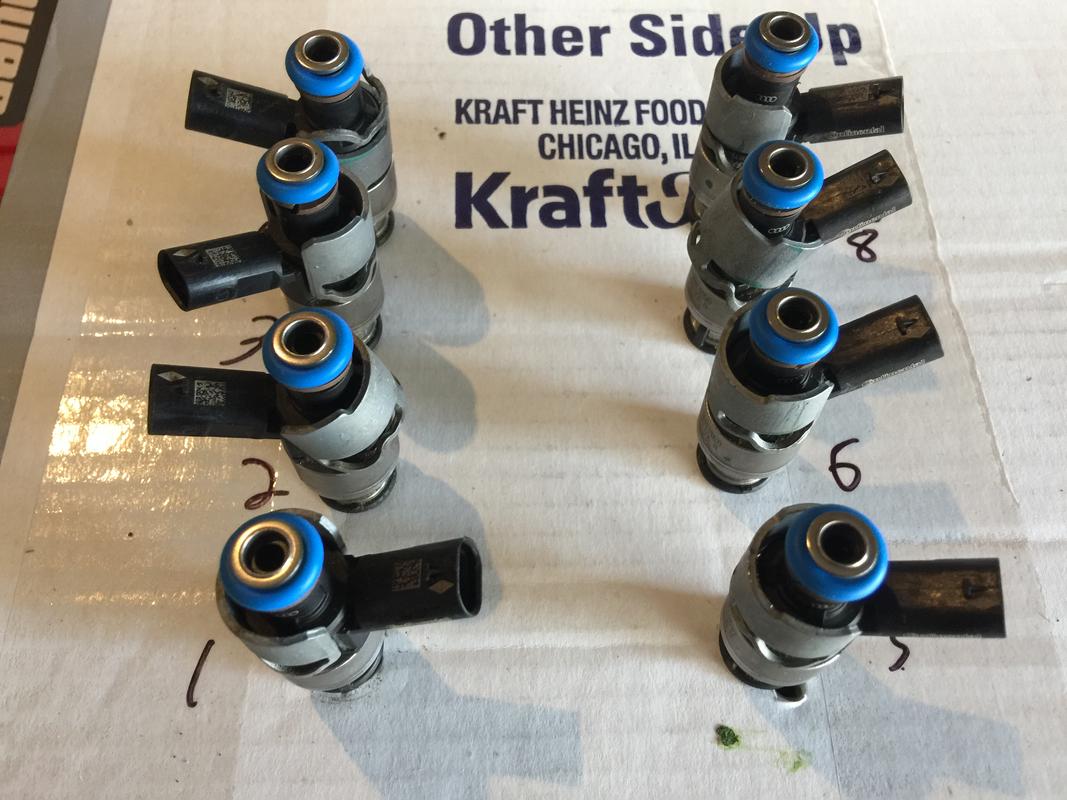
I took the injectors and punched holes in a cardboard box, labeling each injector so I know which one goes where. No real “need” to do this but what the heck. The new gaskets are already on (top o-rings are blue in the rebuild kit, the originals were brown).
New LIM to head gaskets but more on that later.
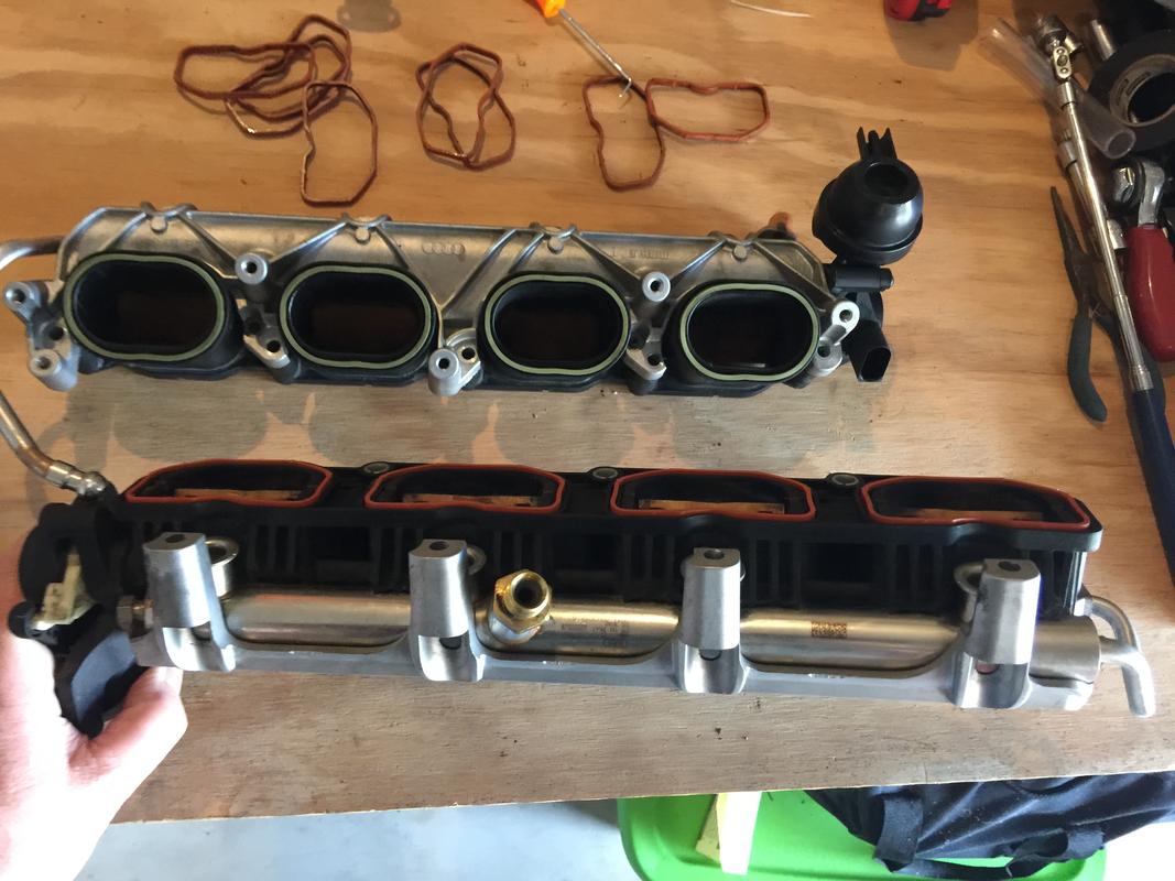
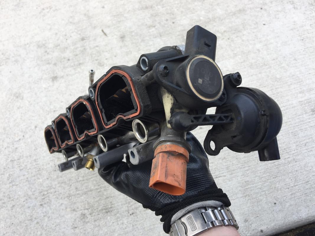
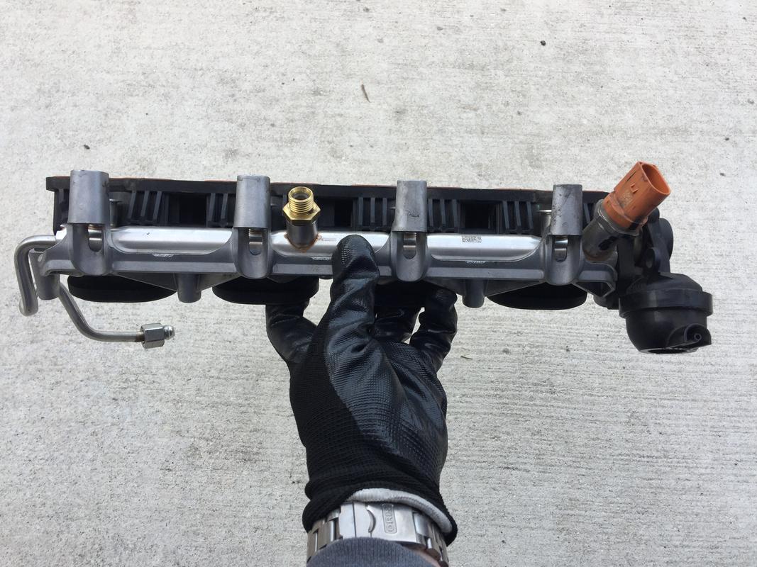
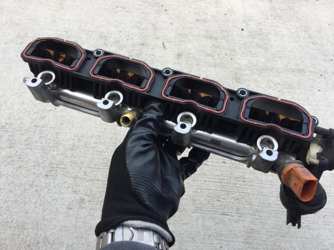
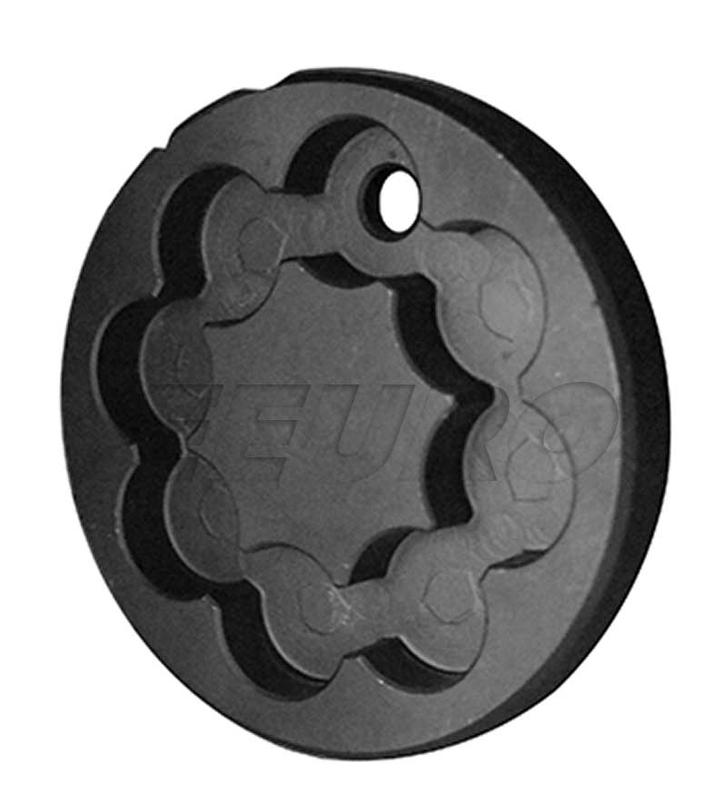
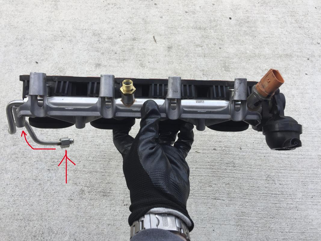
Gratuitous shots of the LIM just because. How often do you actually see them?
Dividers cleaned and ready to be installed after the carbon cleaning.
Carbon Cleaning
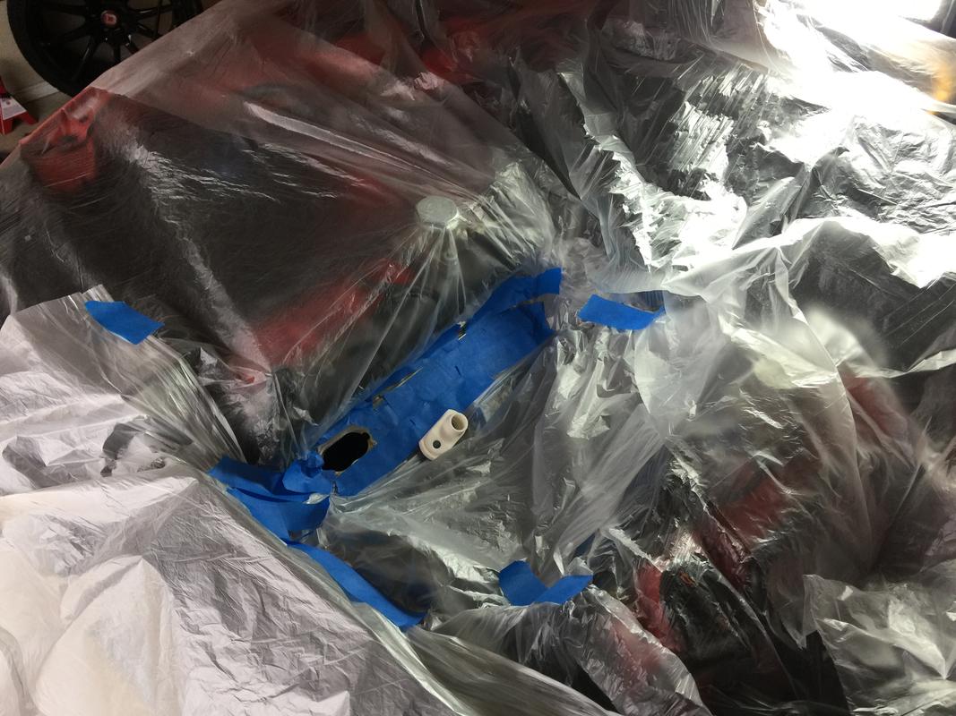
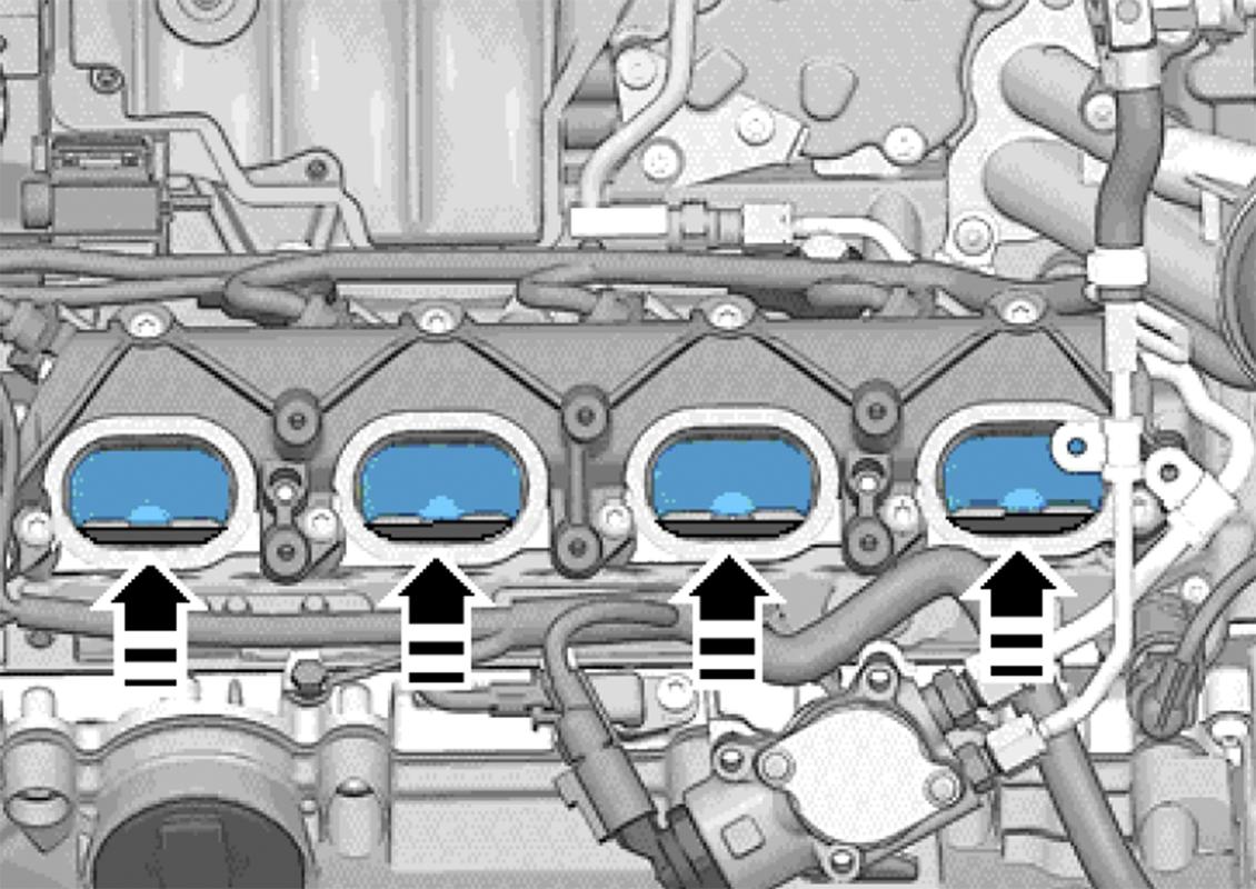
I know this is the step you’ve been waiting for. In the photo below, I’ve taped everything off except the port I’m cleaning. Additionally, I laid drop cloth in all four directions. In the end, the drop cloth, if you’re careful, isn’t necessary.
IT IS necessary to tape off the ports you’re not cleaning and TAPE OFF THE INJECTOR PORTS TOO!
After I was done cleaning a port, I’d tape it back over and mark the tape with an X.
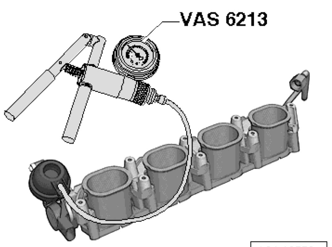
With the car in the service position, there’s enough room to get a 3/8" breaker bar down there. I’d originally purchased a specialty tool for Audi which supposedly fits in the crank’s snout. See pic.
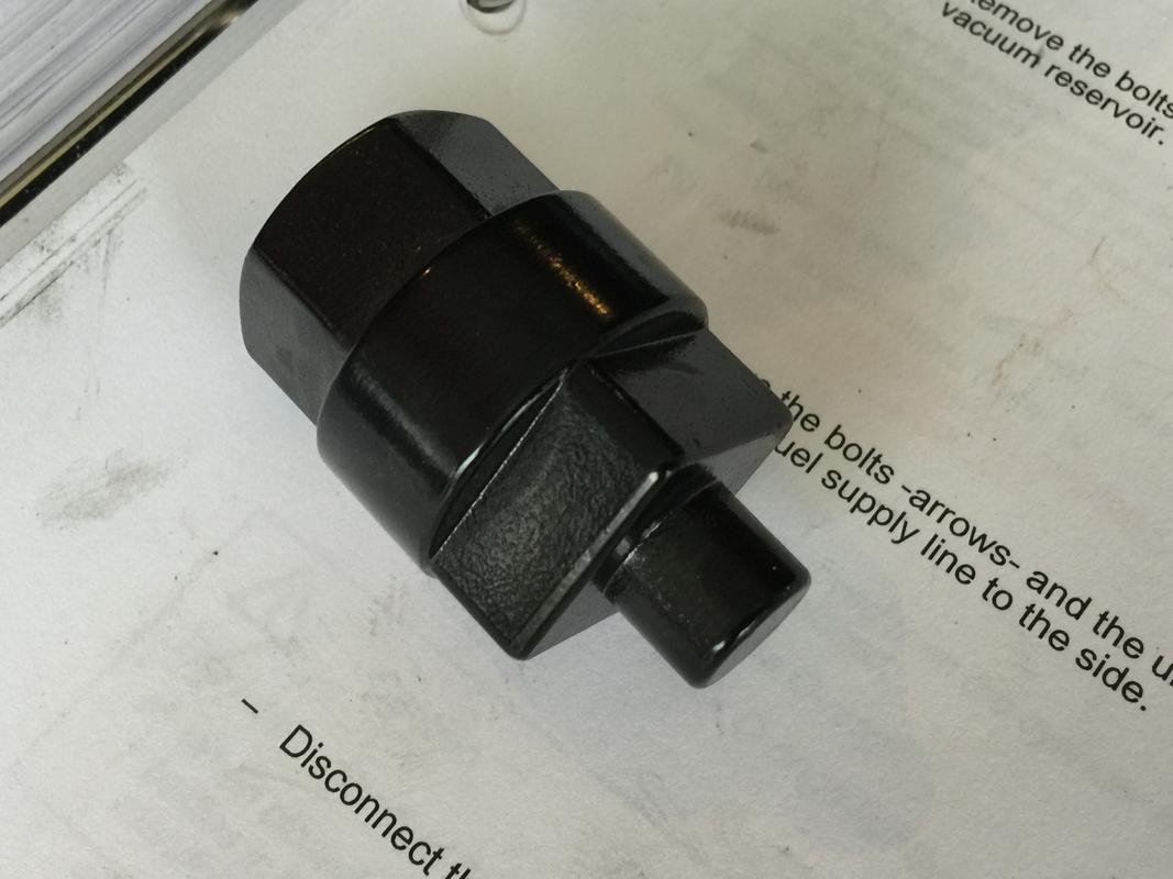
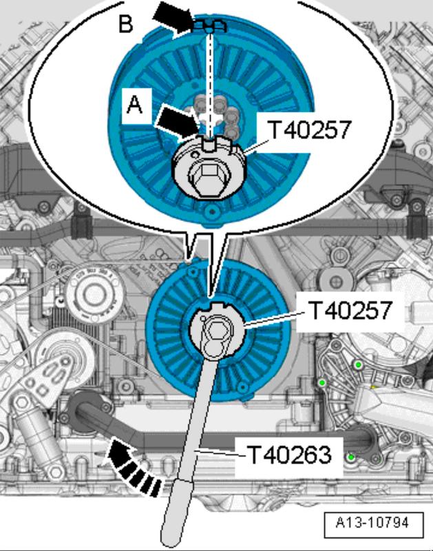
Well, it does not fit. In fact, there’s nothing but a bored out cone in the center of the crank. No threads, nothing. Somehow I had the wrong adapter. What you actually need is part number T40257 which fits over all the harmonic damper bolts. Here’s one place to get it but they’re on eBay as well; http://www.baumtools.com/shop/VW-Audi/13-Engine-Crankshaft-Pistons/T40257-VAG-Crank-Turning-Too#.XACeui3MzOY
I was in a pinch since I didn’t have the proper tool. The harmonic damper bolts are M8 triple square bolts. By inserting the bit in just one, you can easily turn the engine with the injectors removed. It was actually shocking how little friction there was. To be safe, I’d get the adapter. It’s like $35.
Shot from the FSM. Just ignore the arrows and other bit, just showing you how the adapter fits in there and what the crank end looks like.
Once you have your bit and breaker bar attached, rotate the crank until the valves in the cylinder of your choosing are closed. Just watch the valves aided by a flashlight as you rotate the crank slightly. It’ll be obvious when they’re closed and they’ll stay closed for a decent sized duration of crank rotation. Another little tip…usually one or two other ports are fully closed. This’ll save you time rotating the crank.
Test that they’re closed by putting a bit of gas in the port with a syringe, carb cleaner even. If, after a minute or two, the gas is still in there, you can begin carbon cleaning with the walnut shells.
My logistical modus operandi was as follows:
-Blast with walnut shells moving the nozzle around to try and get all areas of the port.
-Flip the adapter 180 degrees and repeat.
-Remove the adapter and inspect
-Go over the ports and valves with the picks, loosening carbon that’s stuck in the crevices of the valve seat as well as behind the valve guides (two worst spots)
-Put the adapter on, switch to the air nozzle, blow compressed air in and suck the chunks out
-Blast again, repeating the 180 degree rotation
-Pick at everything again, blow out with compressed air
-Blast once more and then blow out with compressed air
-Spray in carb cleaner (not carbon deposit cleaner) and wipe the ports out with disposable paper towels. Rinse and repeat until the runner walls and valves shine.
-Tape the port back over, mark with an X and move on to the next one.
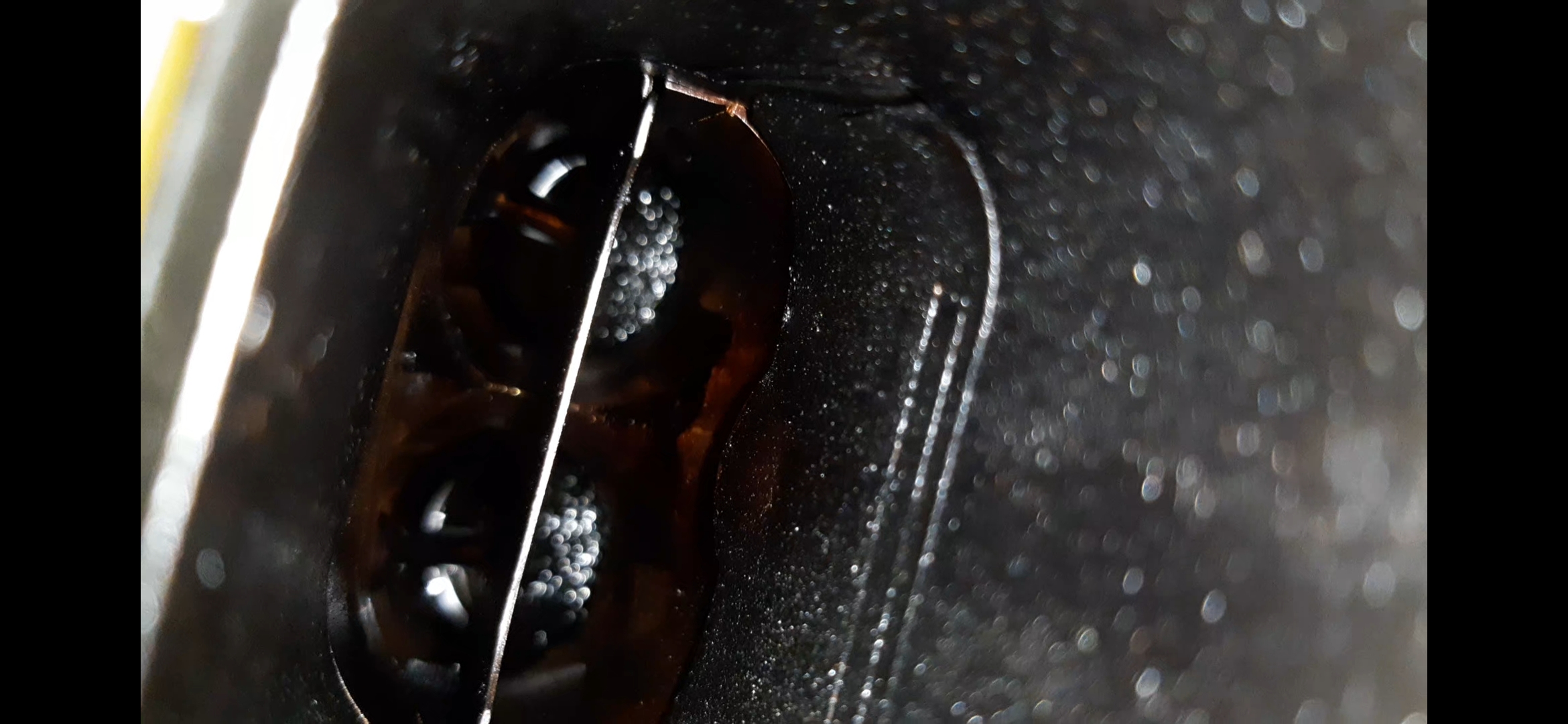
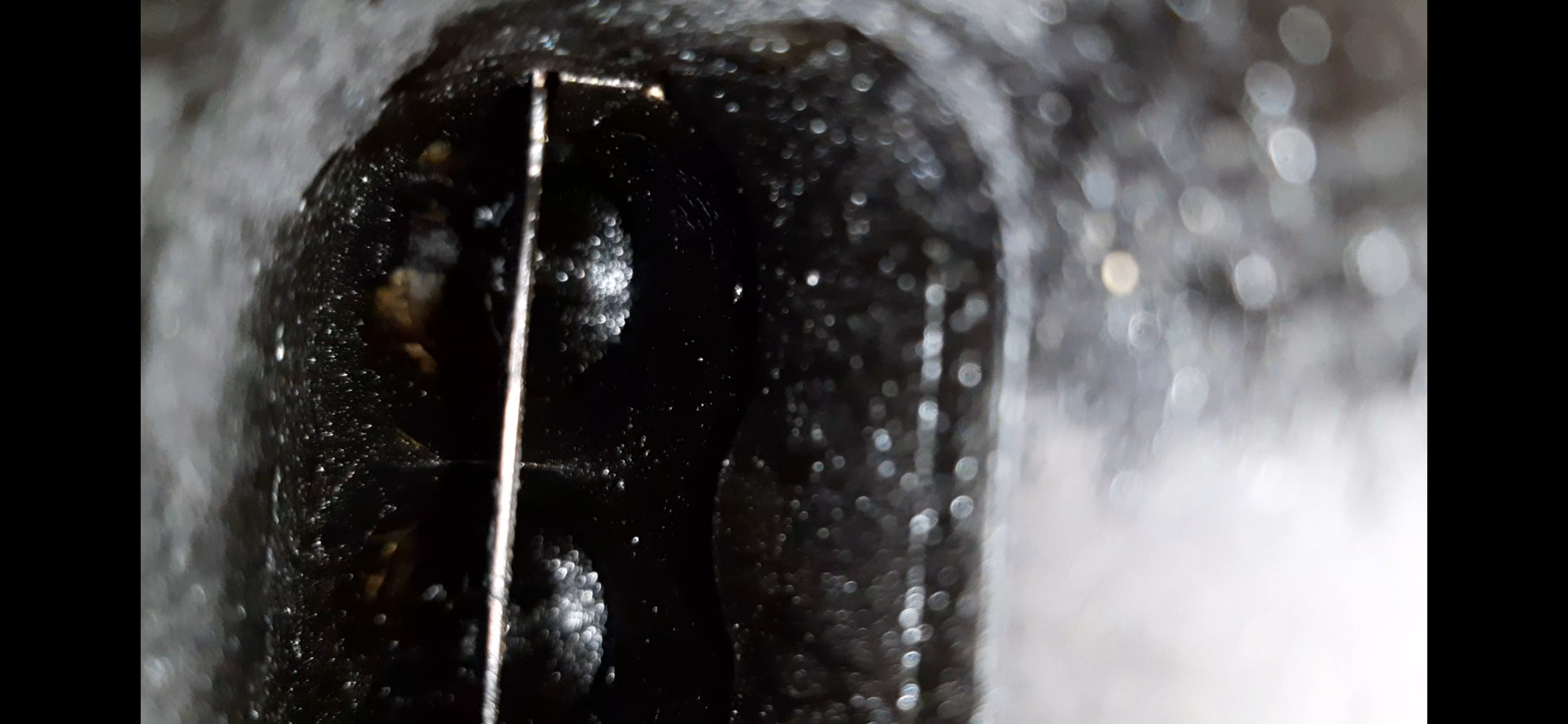
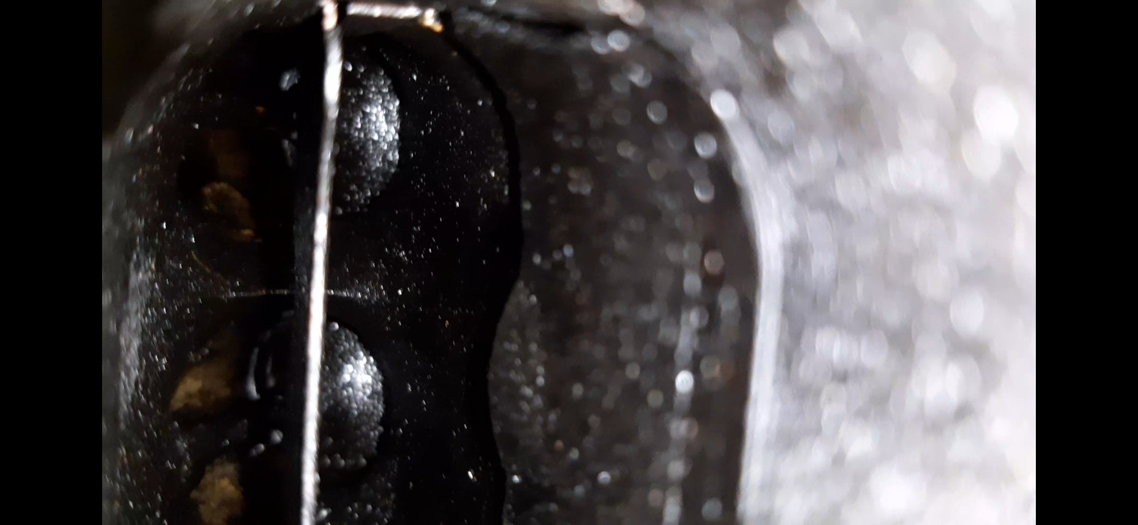
Here’s a short teaser video of what the process looks like
[video=youtube_share;zrbkQCK1EZc]https://youtu.be/zrbkQCK1EZc[/video]
Once you get through with carbon cleaning the ports, we’ll want to take several preparation step before reassembly.
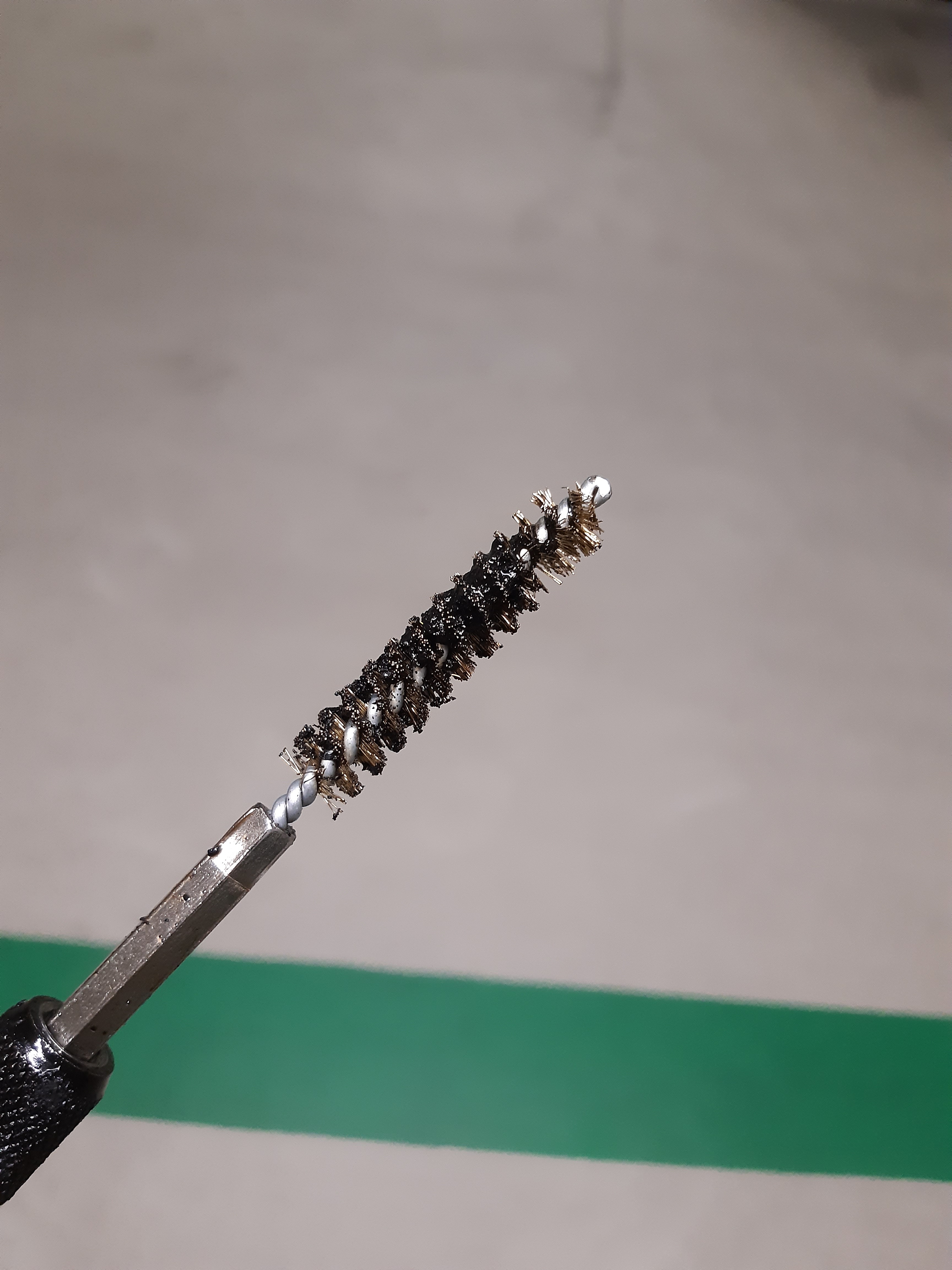
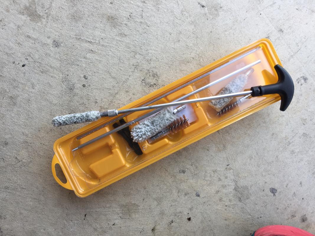
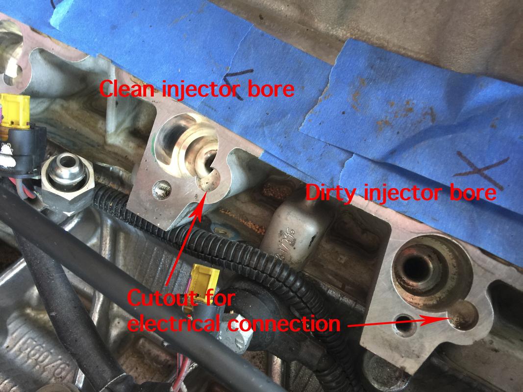
Since the injectors are out, the injector ports in the head need to be cleaned and spotless. There is a factory service cleaning kit that you can probably track down or even purchase small diameter twisted wire nylon or soft brass brushes. A rifle (gun) cleaning kit also works. I bought mine at Walmart for about $7.
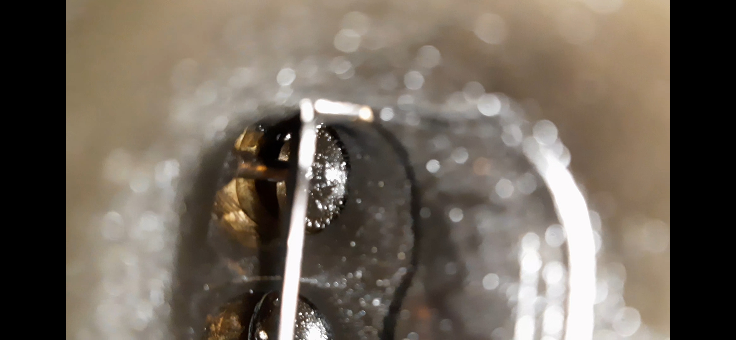
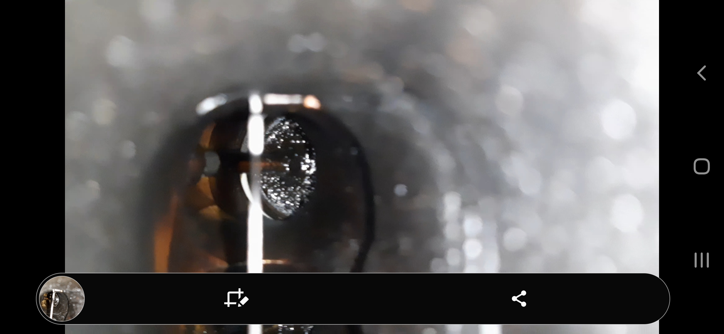
I did clean out the bores by shop vac and hand first to remove any grit. Using the brushes and carb cleaner left the injector port walls with a mirror finish. I also cleaned the smaller bore where the injector nose/seal sits.
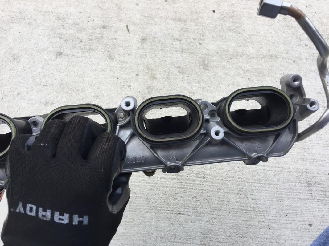
Clean injector ports and the dividers reinstalled.
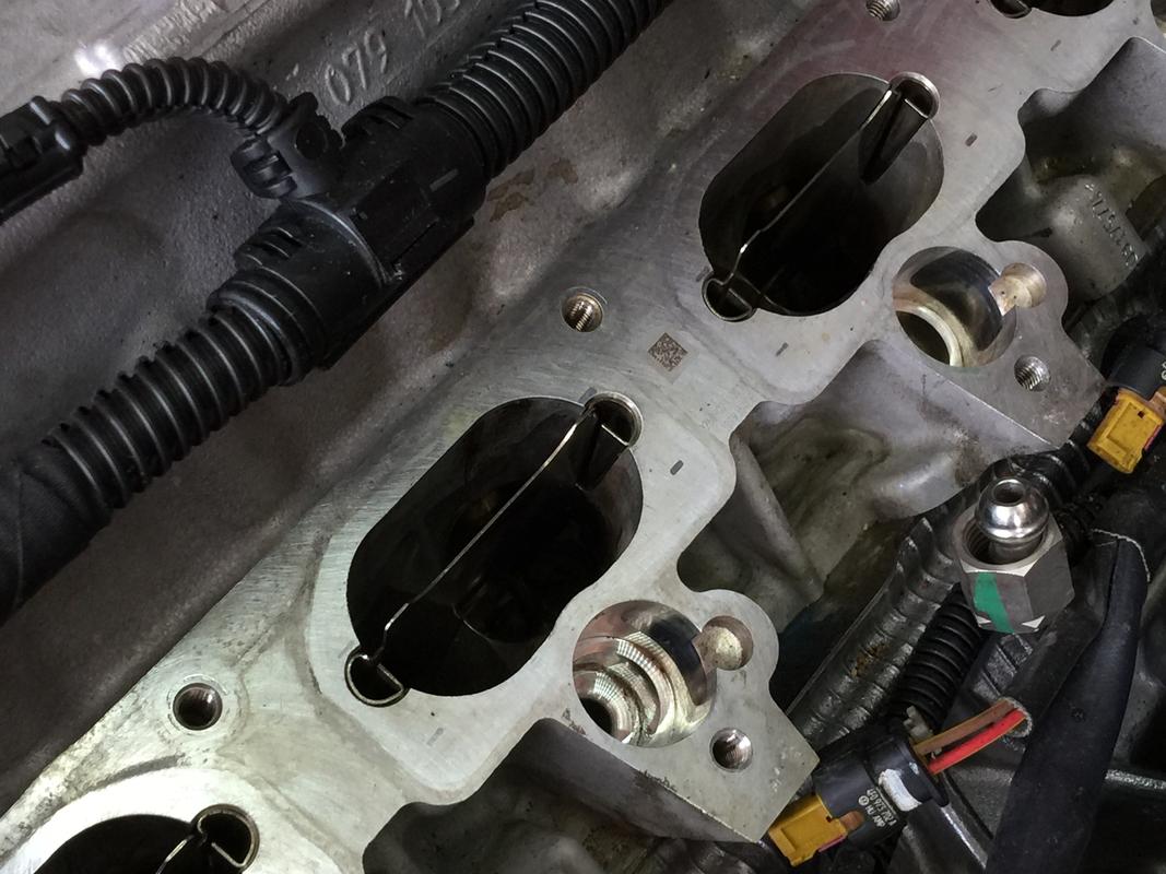
With the injector ports cleaned, plug them up with some paper towel so nothing falls in them. Make sure the rest of the mating surface between the head and where the lower intake manifold sits is completely clean. Wipe it down with your cleaner of choice and finish off with denatured alcohol. Spotless is ideal.
You can also re-install the port dividers. Remember, the dimpled protrusion goes on the down side.
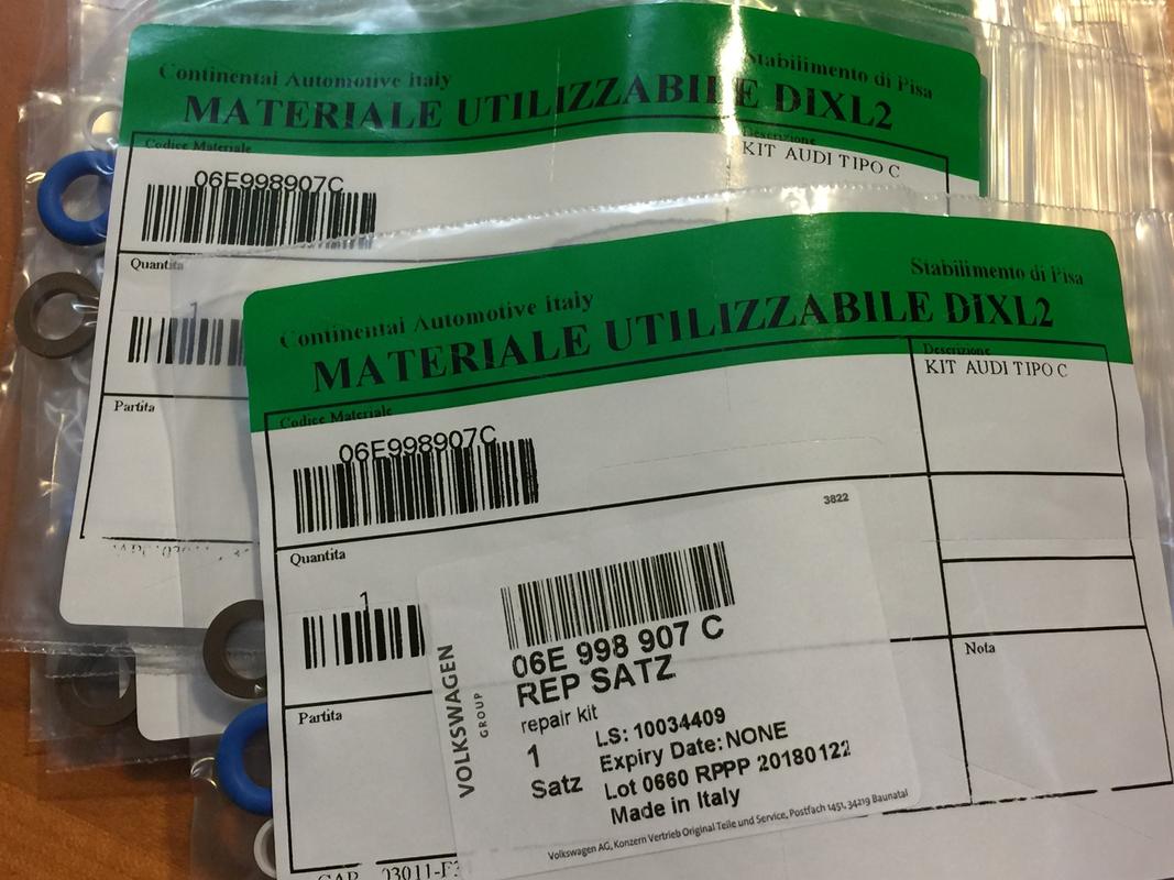
To R&R the injectors, you’ll need the rebuild kit which consists of a new teflon seal, a top o-ring and a split ring shim. You can only buy them as a kit. Each kit contains these three elements so you’ll need eight kits. ECS does sell the kit. Alternatively, if you’re an Audi Club member, the 10% discount actually makes it a slightly less expensive alternative. My dealer does not stock the kits. I had to overnight them from the Fort Worth distribution center. It was an extra $14. Won’t break the bank but do plan ahead and have the kits prior to pulling the injectors. Worst case scenario, you can send back unused kits if you manage to have an injector or two that decide to stay put.
The kits. Note they’re made in Italy.
Here’s an injector prior to having the new kit put on. The original top o-ring is brown, the new are blue. The shim and the teflon seal look the same.
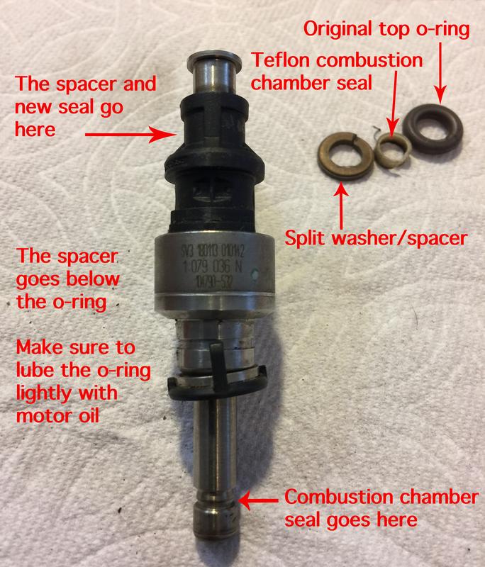
To get the old teflon seal off, use a small utility or hobby knife to simply cut them off. Be gentle as you don’t want to gouge the injector with the blade. The o-ring comes off easily with a small pick or even your fingers.
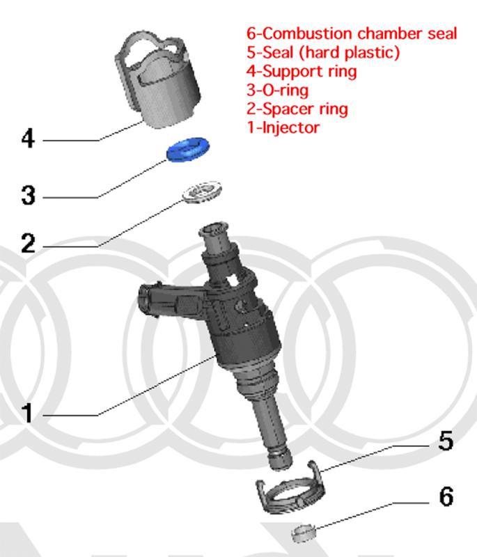
Here’s an exploded view of all the injector components from the FSM.
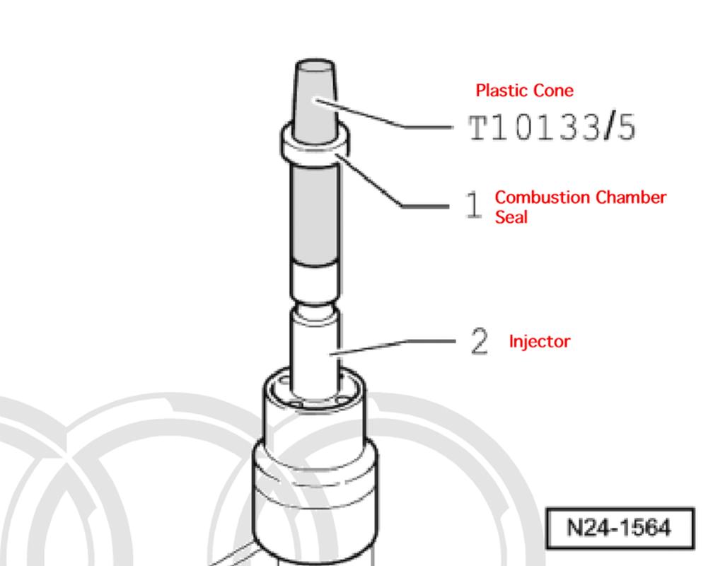
The tricky part to the injector rehab process is getting the teflon combustion chamber seal installed. The seal itself is malleable. It’ll stretch and you can also compress it. As it comes out of the package, the seal’s inside diameter is smaller than the outside diameter of the the injector’s tip. The seal sits in a groove with a smaller outside diameter than the shaft. To get the seal onto the injector, it needs to be expanded. The best way to do this is with a cone.
Here are some excerpts from the FSM using the specialty tool which costs about $200. I’d recommend purchasing the tool but it can be done without it if you’re careful and detail oriented.
First step, slide the seal onto the expansion cone.
Second step, push the seal onto the expansion cone further with other half of the audi tool using a twisting motion.
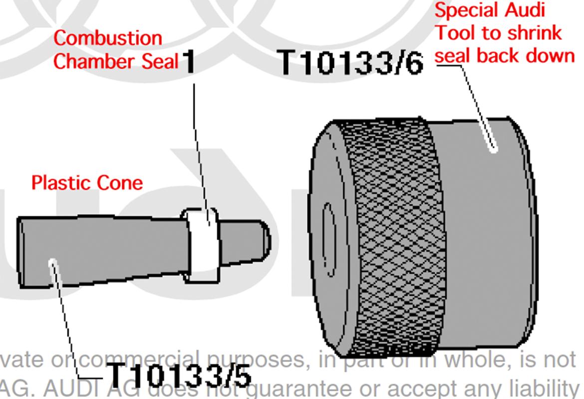
Third step, line up the expansion cone and twist with the other half of the Audi tool until the seal slides over the end of the injector and into the groove.
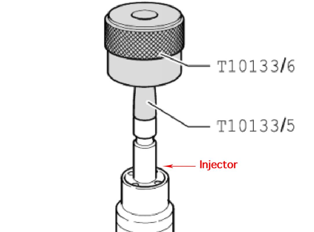
With the combustion chamber seal in the injector’s groove, continue to twist the tool and it’ll shrink the seal back down.
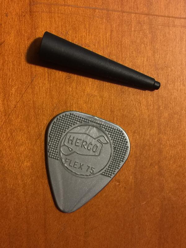
I had a bit of luck rigging up my own kit. I had an old brake bleeder I’d pulled out to use the vacuum pump to pull back the flappers on the LIM. It included a number of adapters designed to fit various hose sizes. The adapters were cones, made of a very hard, smooth plastic. It almost has a silky feel to it if that makes sense and a very low coefficient of friction. Since it was a long cone, I just cut it at the point where it was the same size as the end of the injector. Perfect! I also had a small plastic cylinder that was just the right size to push the seal on and expand it. Once you get to a certain point, you can actually do it with your digits. I wore clean latex gloves when handling the seals.
Here’s the cone I used, next to a guitar pick for size reference. Worked like a charm.
Now I did not take any photos of me shrinking the seals back down as it’s a two-hand, delicate job and I wanted to concentrate. I took a properly-sized zip tie (same width as the seal) and reversed it so the smooth side was on the inside. I shrank it down so that it still fit over the seal and then used a pair of pliers to press against the outside of the zip tie and worked my way around the outside of the seal. It won’t completely shrink back down but it was enough that the injectors went in easily (with a bit of pressure which is normal) and I’m not experiencing any issues.
I’m a sticker for doing things the right way and I honestly recommend getting the tool. I was in a bind, not knowing how easily the injectors come out and it caught me unprepared. Live and learn. There were enough people online that do it with the zip tie method that I felt comfortable doing it that way.
One you have the injectors rehabbed, insert them back into the injector bores. DO NOT PUT ANY LUBE ON THE INJECTORS! NOTHING ON THE TEFLON COMBUSTION CHAMBER SEALS. VERY IMPORTANT!
The injectors should slide in 80% of the way and it’ll require a bit of careful force to push them in all the way. Be gentle. Take careful note of the cutout in the head for the injector electrical connector and make sure it’s oriented in the right direction before trying to push it all the way in the bore.
Closeup of an injector almost seated in the bore. Find a socket that sits flush with the support ring and use a rubber mallet to softly tap the injector in place.
LIM Reinstallation
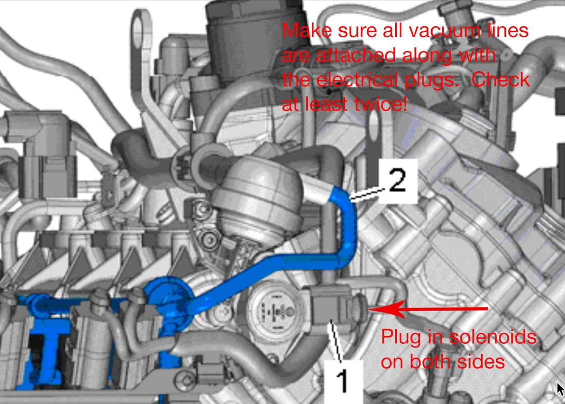
With everything clean and the injectors in place, it’s time to reinstall the LIM. Make sure you’ve lubed the injector o-rings. I also put a thin coat on the injector bungs in the lower intake manifold.
You’ll want to clean out the LIM runners and flappers a bit as they can become caked with oil over time and stick open/closed. Clean them and then make sure they’re functioning properly with the vacuum pump. Clean the green, LIM to UIM gaskets on top with denatured alcohol.
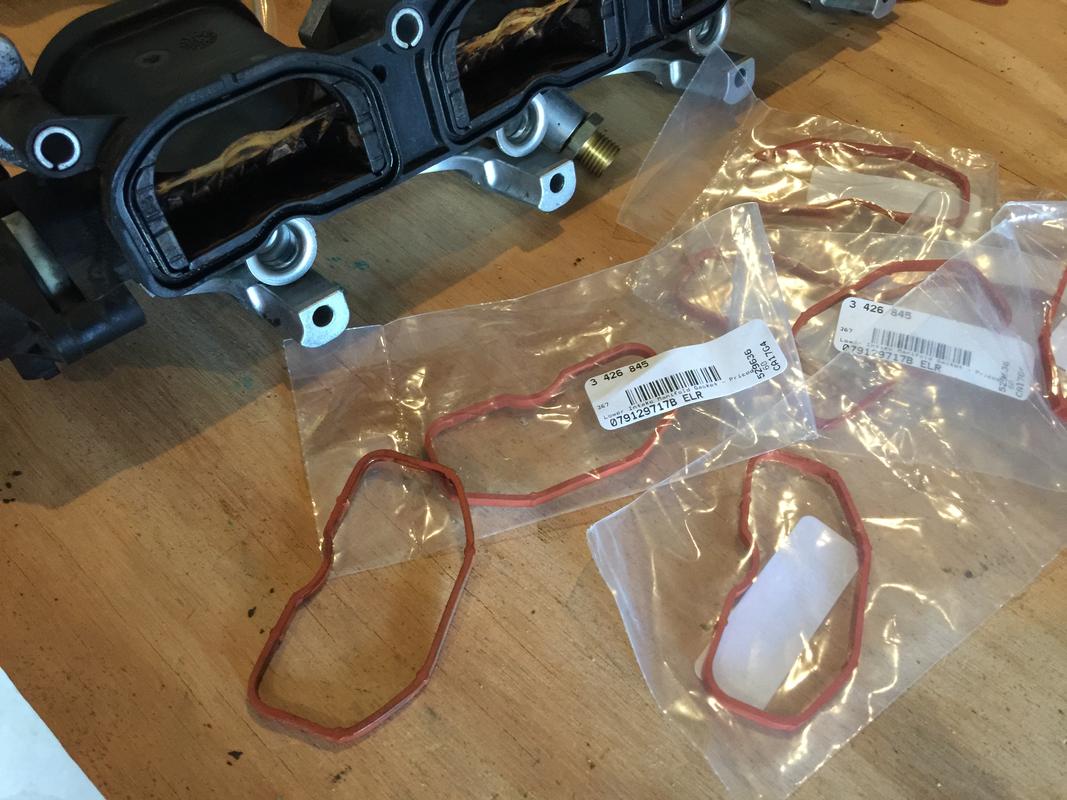
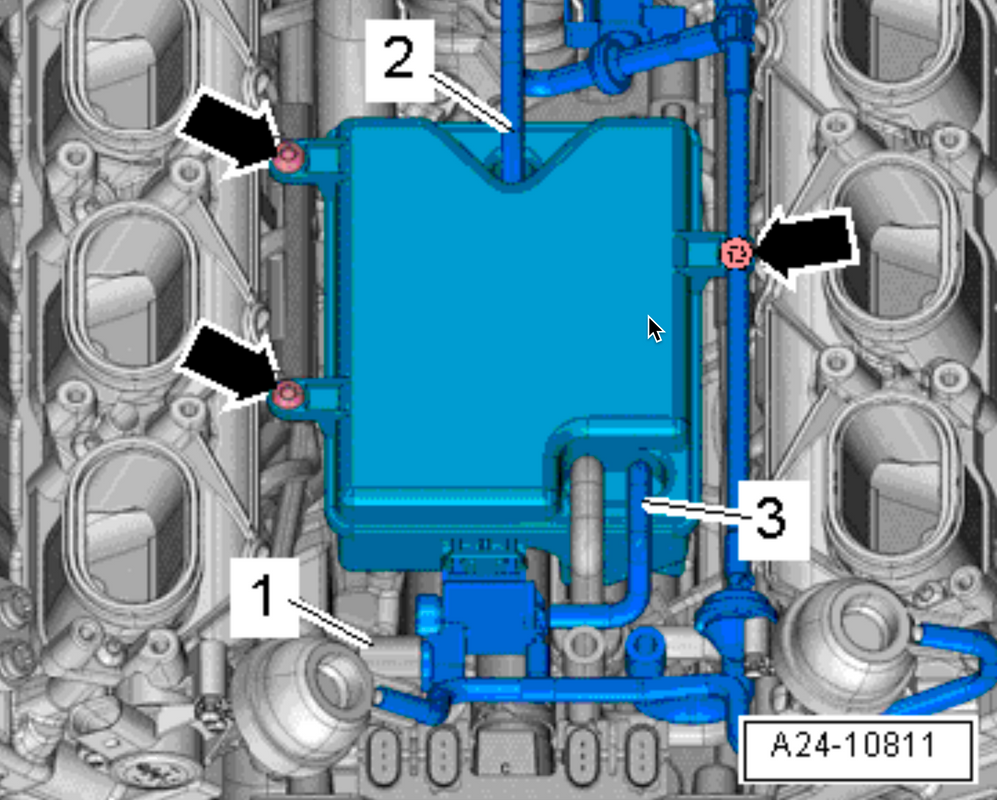
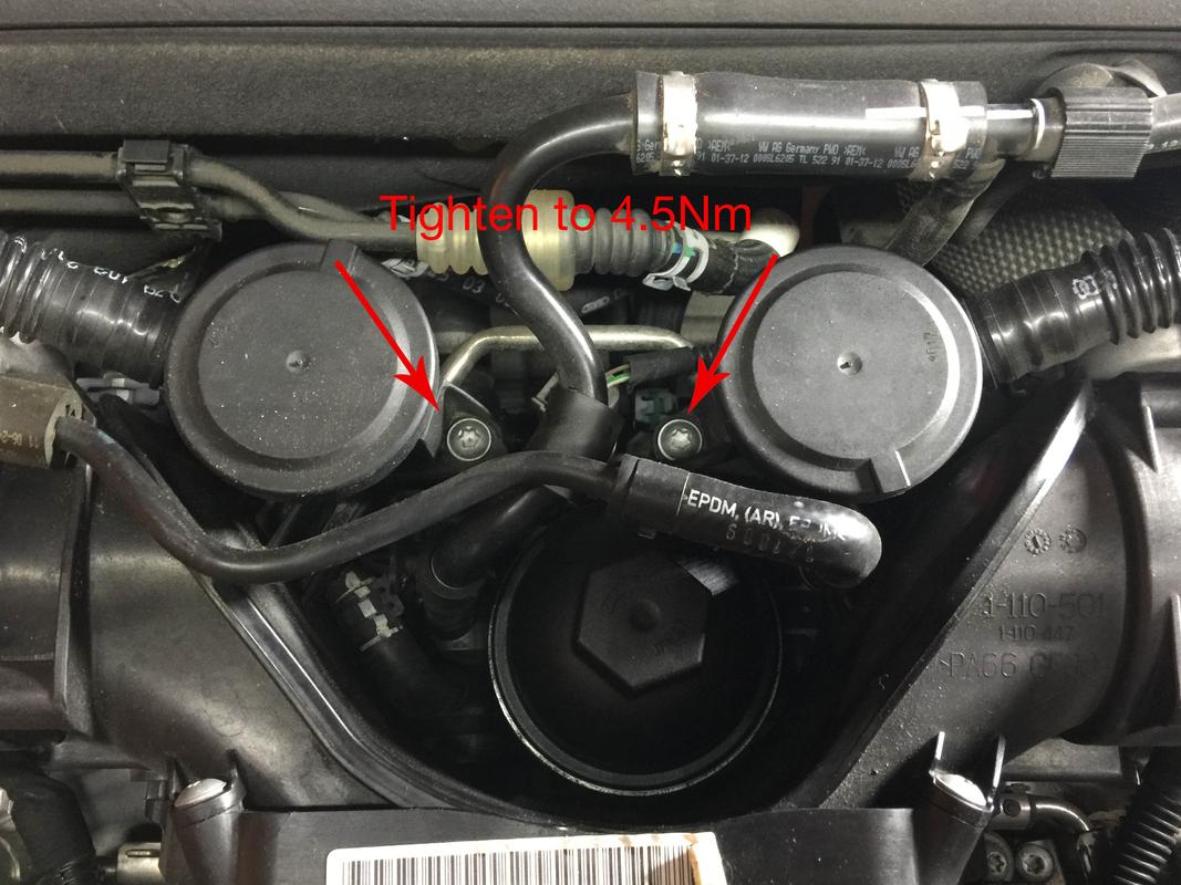
The last thing you’ll want to do before installation is install the new LIM to head gaskets. They’re the red ones on the bottom. They’re stuck in there somewhat but they come out fairly easy with a small pick. Install the new ones by pressing them into place and you’re good to go.
 . I plan on getting this done soon so I’ll look into this page closer. The car is at 46k so maybe within the next 10/15k miles.
 it will defo be easier than putting it into the service position and it will save time bonus !!