The Red Mist, An RS5 Tale and introduction

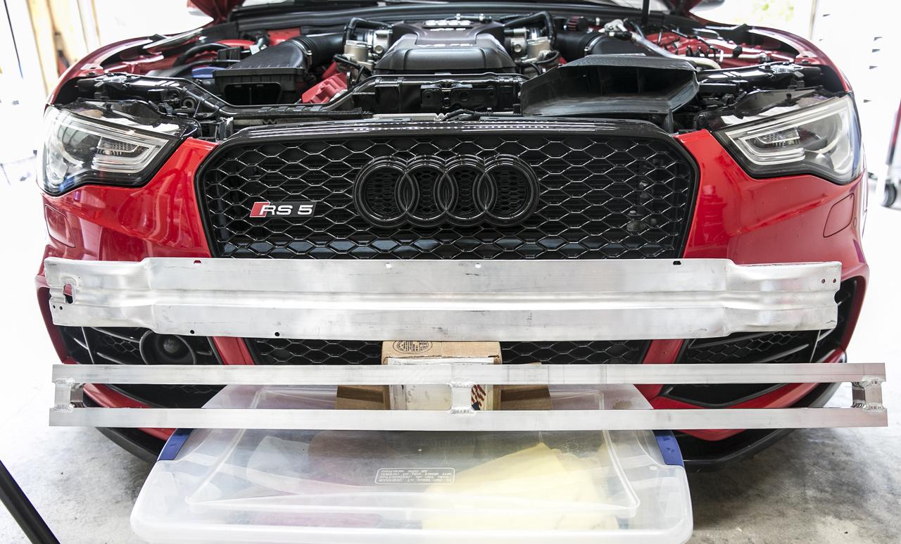
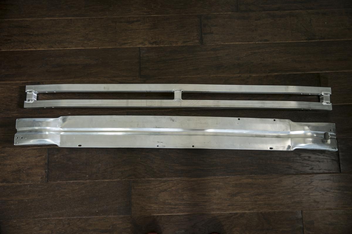
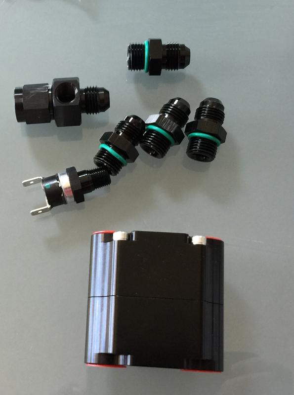
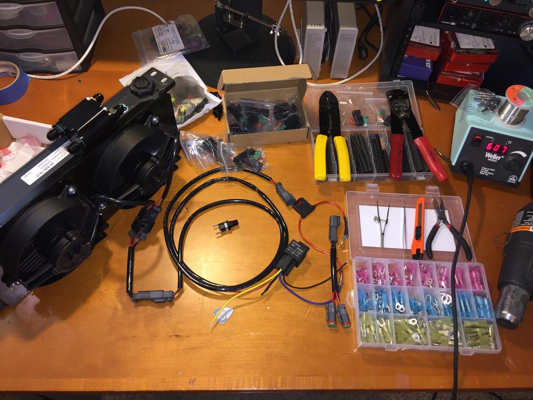
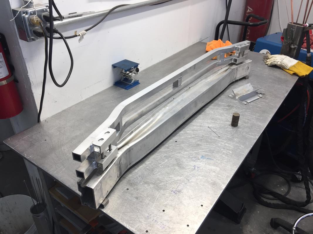
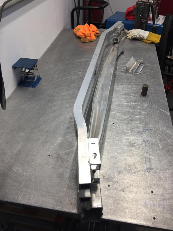
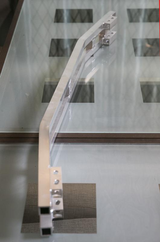
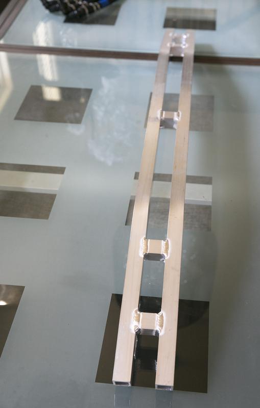
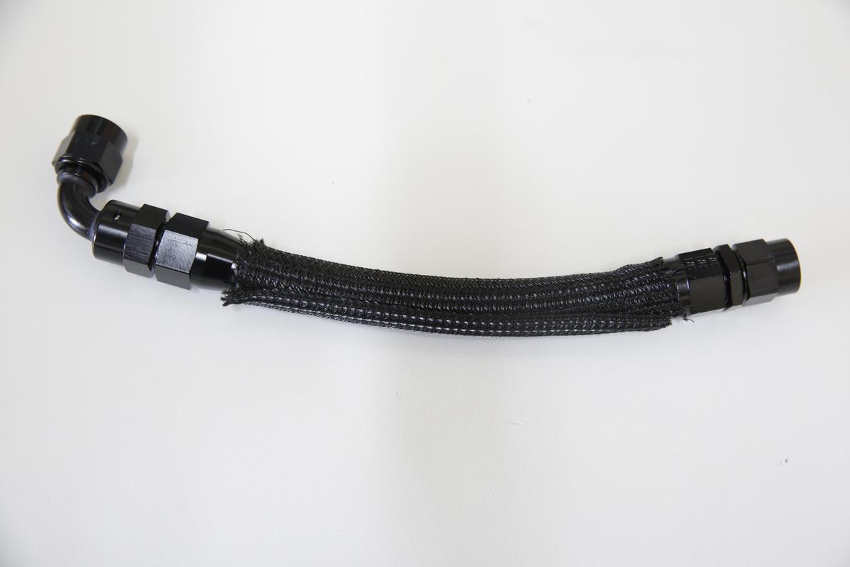
Hey James, the cost of some of these esoteric and model-specific components is pretty high for what they are so I like to keep them intact. If someone wants to return the car back to OEM, it’s easily done. There is one ear (oettinger) clamp which needs to be clipped with a set of bull-nosed pliers but it literally takes three seconds (I shot video of course!). Other than that, it’s really easy to install. I’ll have an installation video as well as written instructions once I have all the final components on hand and at least one assembled for someone else.

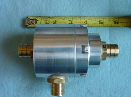
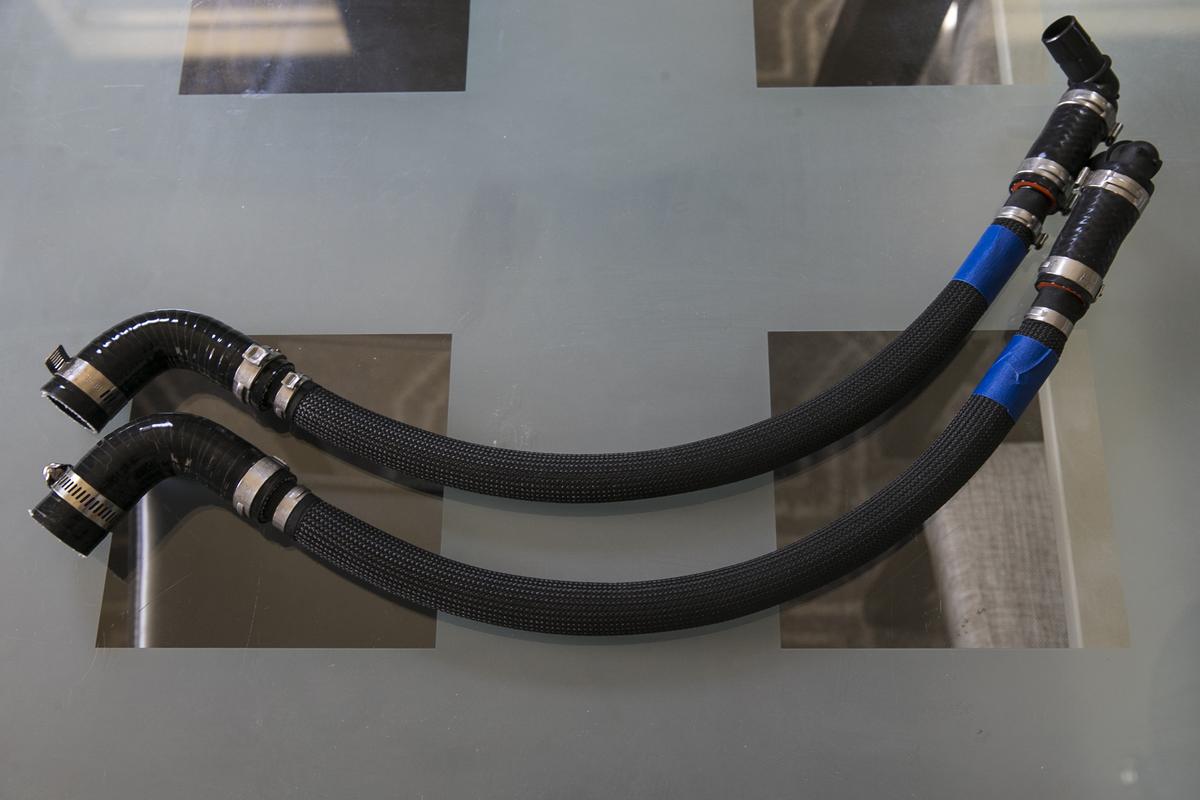
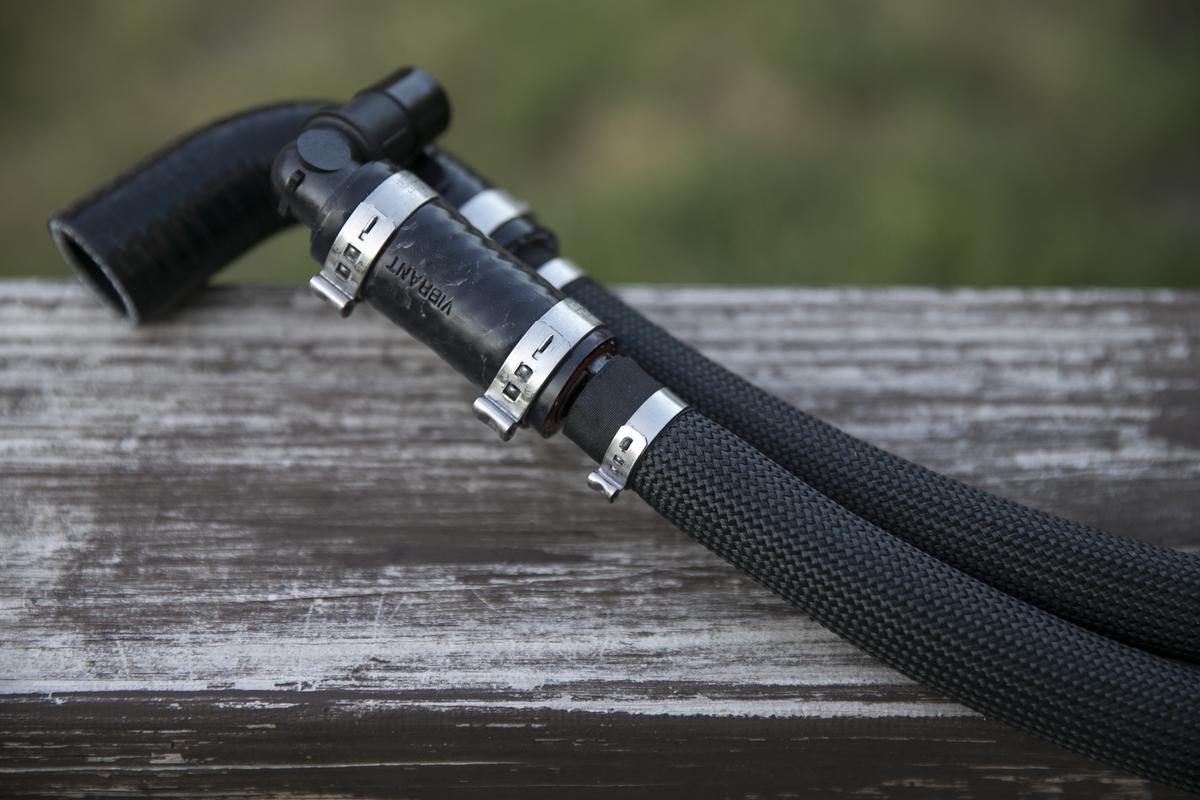
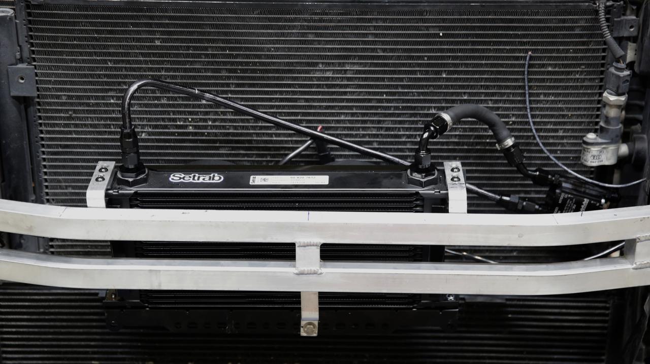
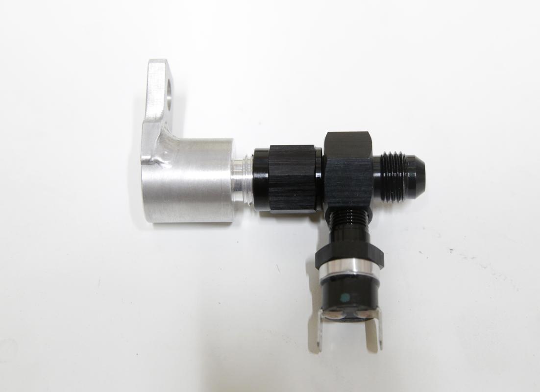
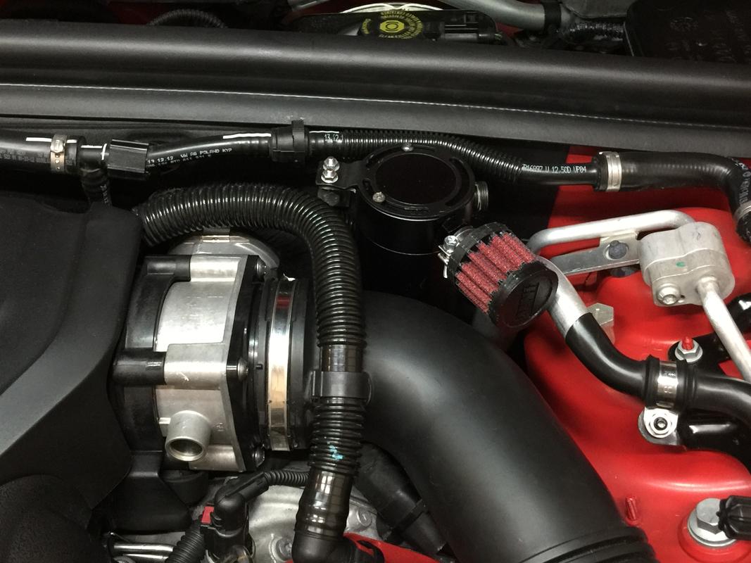
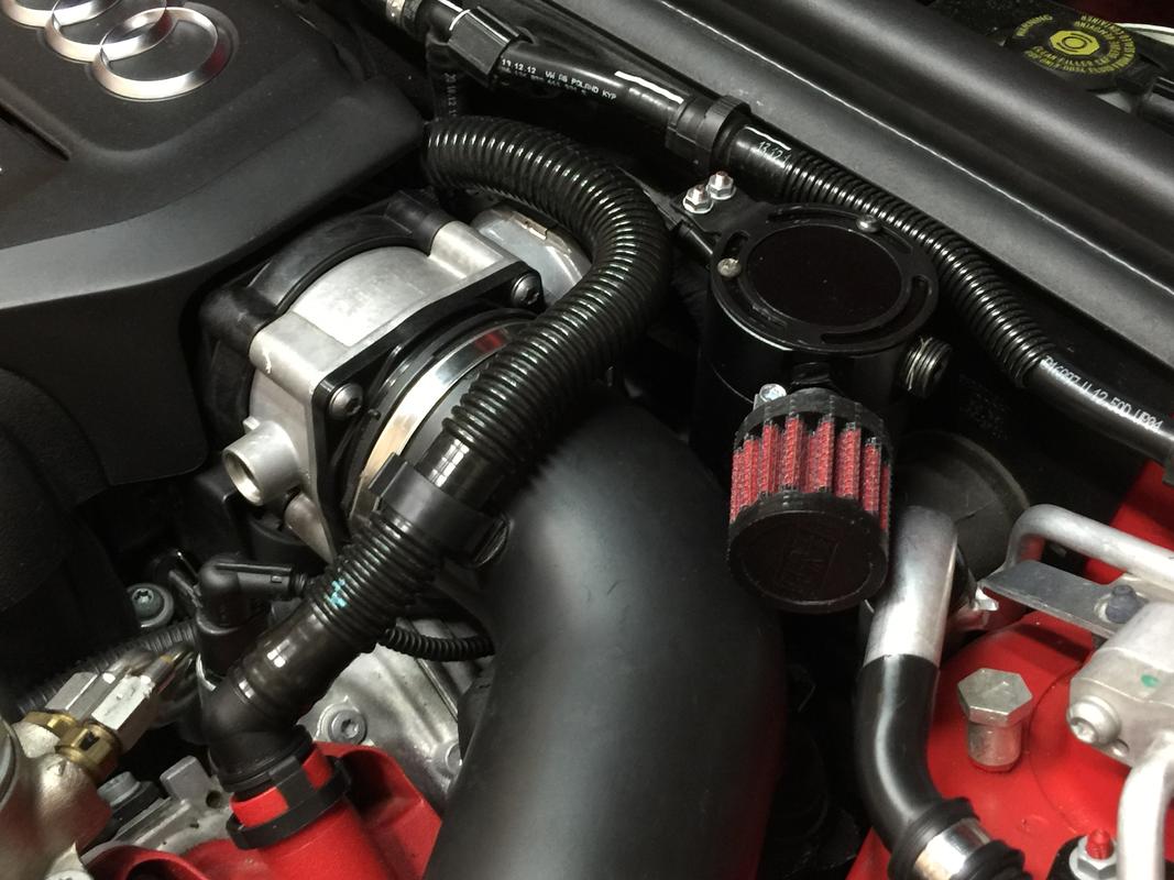
The vented container at the top, that’s actually for the transmission. If you really push these cars (or any S-Tronic) hard at the track or on the back roads of “Mexico”, the OEM transmission case vent can pop open (by design) as the fluid heats up and expands. At the very least, you’ll smell it. Some can bubble out and sit on top of the transmission as well. The contain is designed to prevent both the smell and the fluid escaping. It’s essentially a catch can-like setup but there’s no fluid separation. It’s very similar to a radiator overflow. In addition, drag strip guys can overfill (from the top) the ATF fluid to prevent possible starvation issues under high g launches. I know some of the S5 and S4 guys experience this and as the RS5 gets faster, it’ll be a useful item to have.

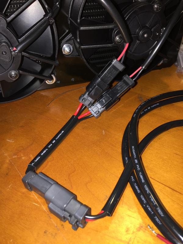
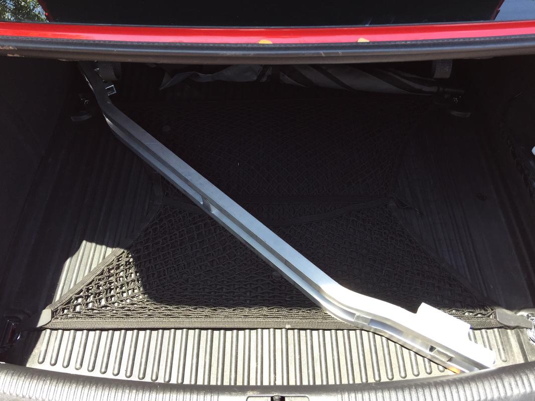
I had a little escaping so I went ahead and whipped something up. The way it’s set up, any fluid is contained in the unit and there’s no smell. As the car cools down, fluid is free to drain right back into the transmission. It’s not as big a problem on the RS5 just yet but track day cars may want to utilize one. I can make more of those as well. Also easy to install surprisingly as I found a clever way to do it from the top of the car. No hand shrinkage required.

The RS3 and TTRS can both experience ATF fluid burps and full-on pukes when tuned. I know one individual who’s actually had ATF fluid up his windshield and over theft side of his engine bay. Not exactly safe on a mid-10 second car and the smell is truly something to be experienced to fully understand. It’s not something you’d want to try and clean out of your engine bay.

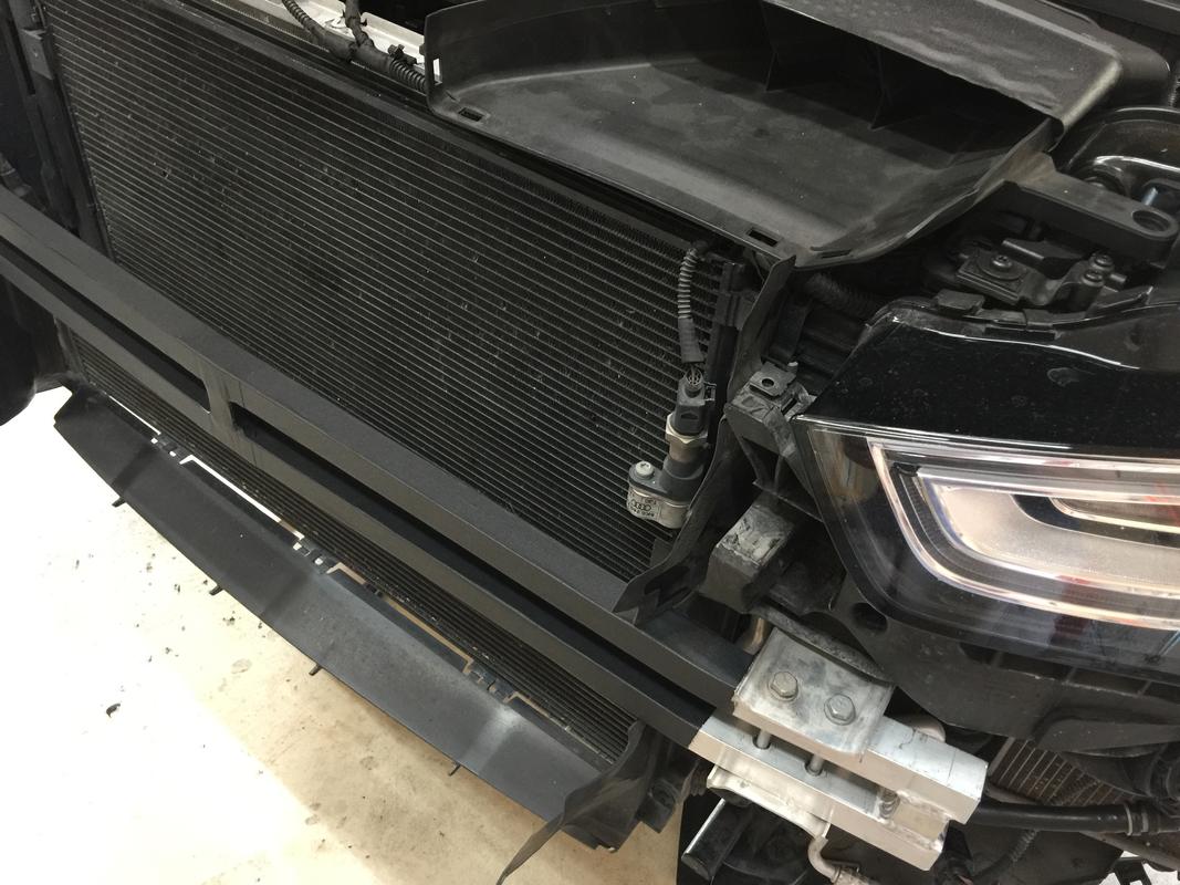
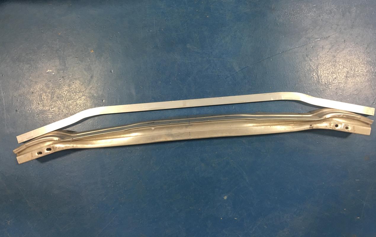
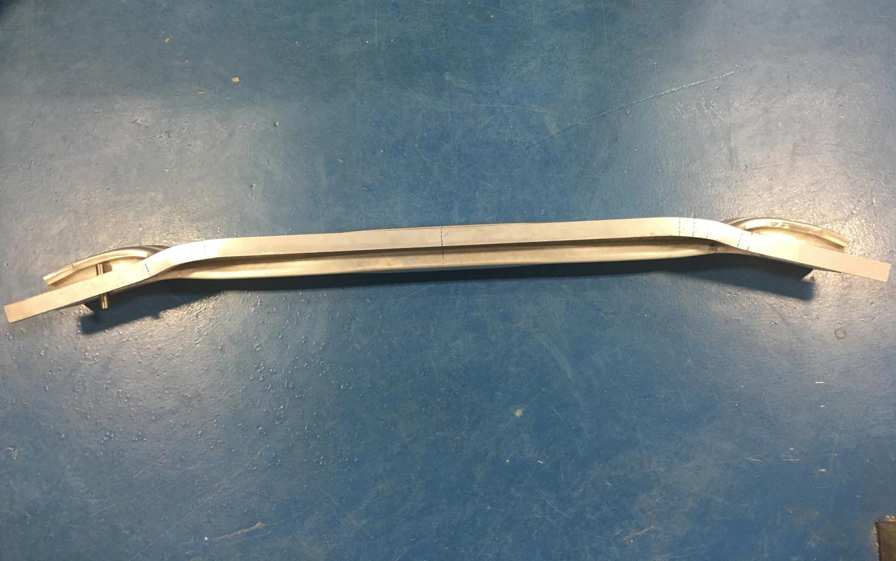
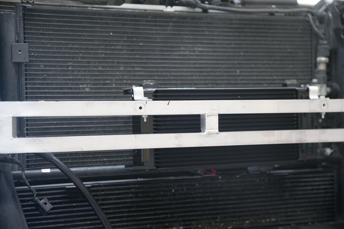
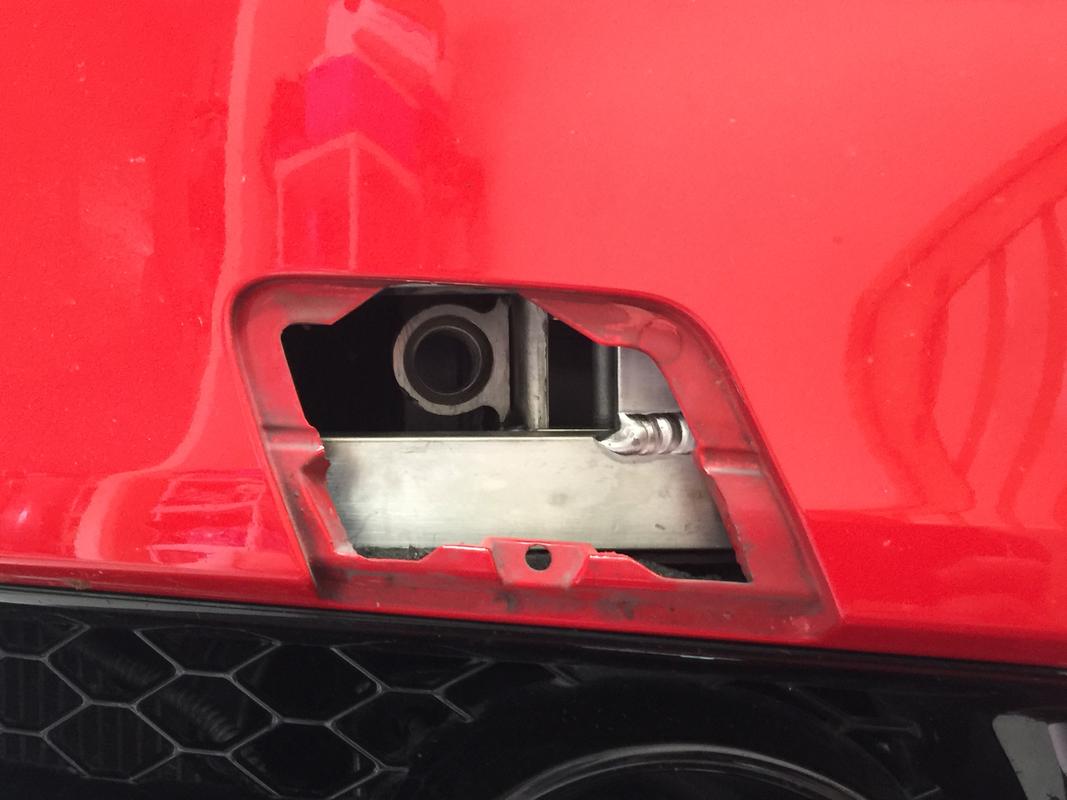
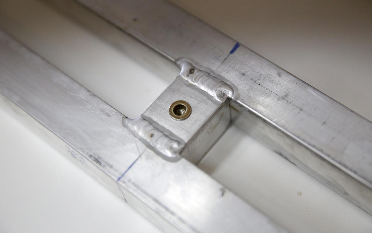
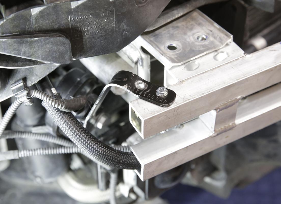
The vent/overflow container mounts on the firewall with a bracket. No drilling, no extra holes or anything. It utilizes existing threaded holes. Fits surprisingly well right there too. No rubbing on anything.


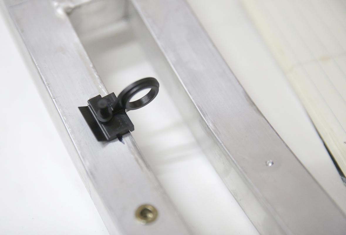
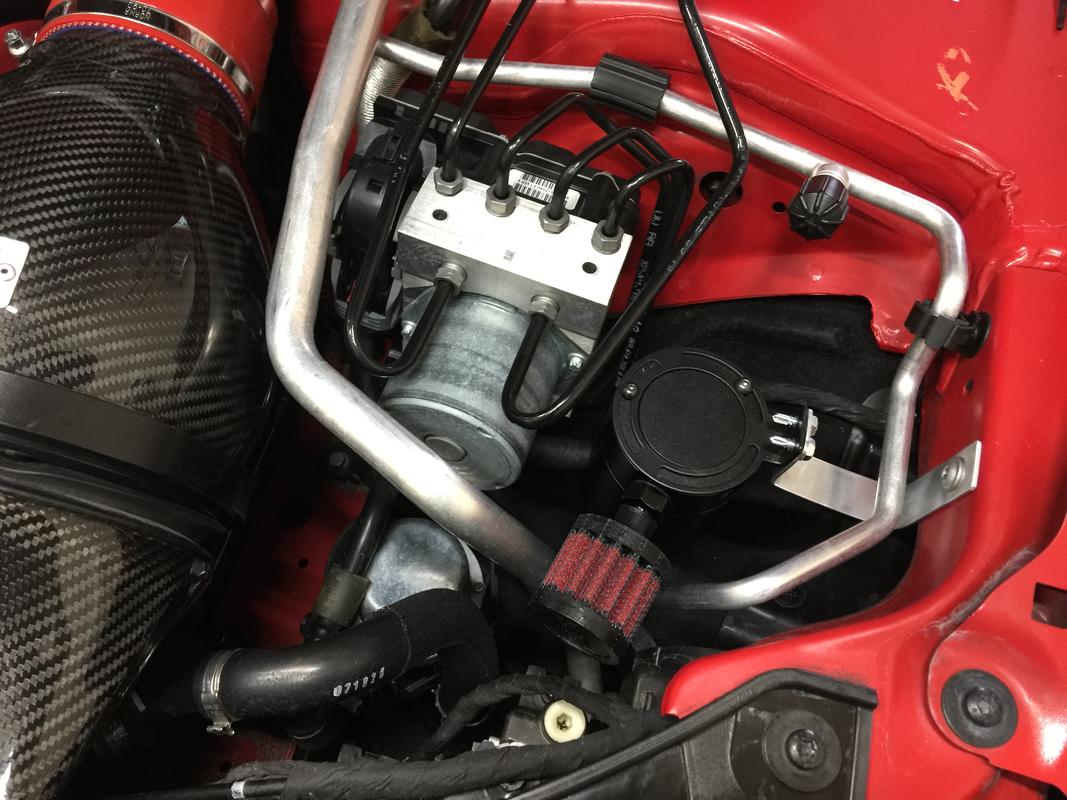
I originally had it near the ABS unit as there was a space and an unused bolt hole. Unfortunately this doesn’t allow for the fluid to drain back via gravity.

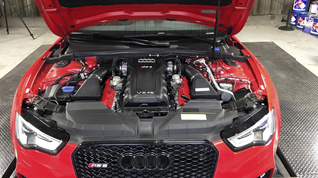
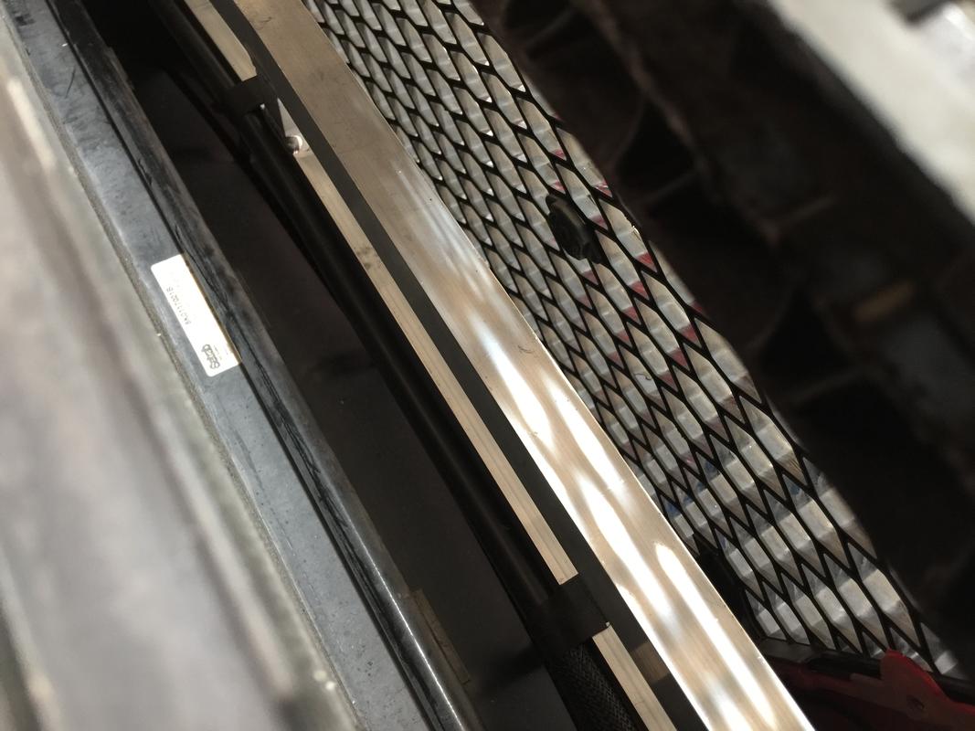
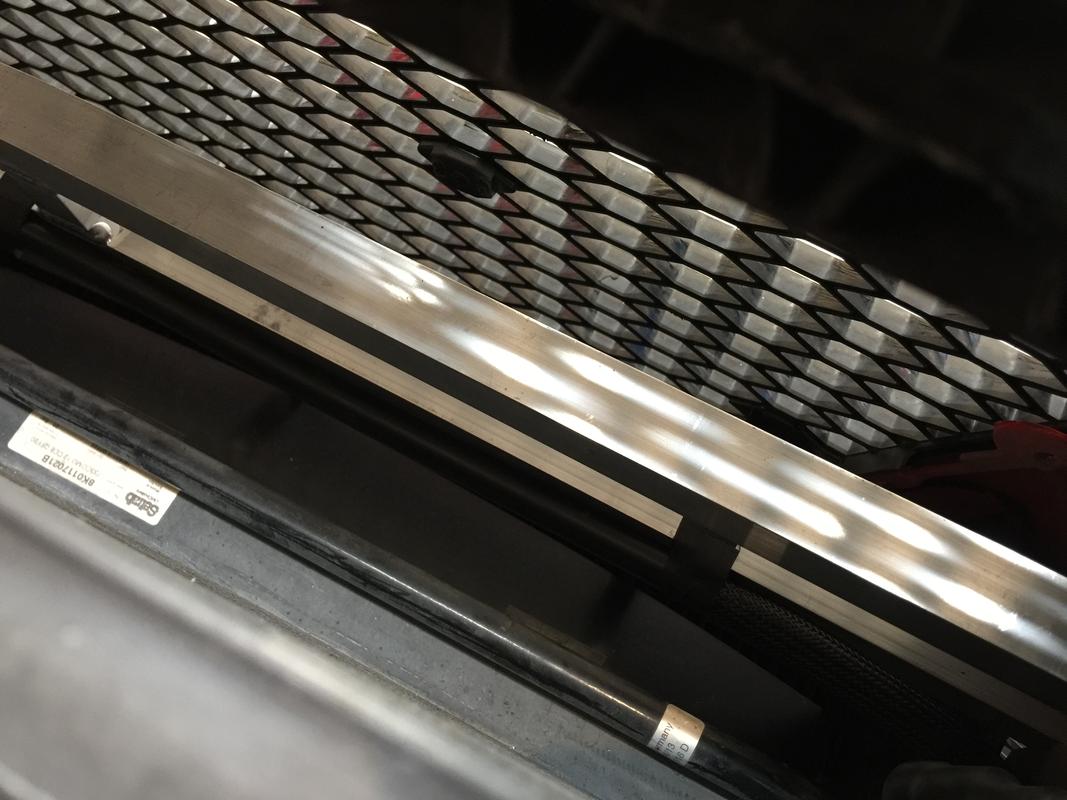
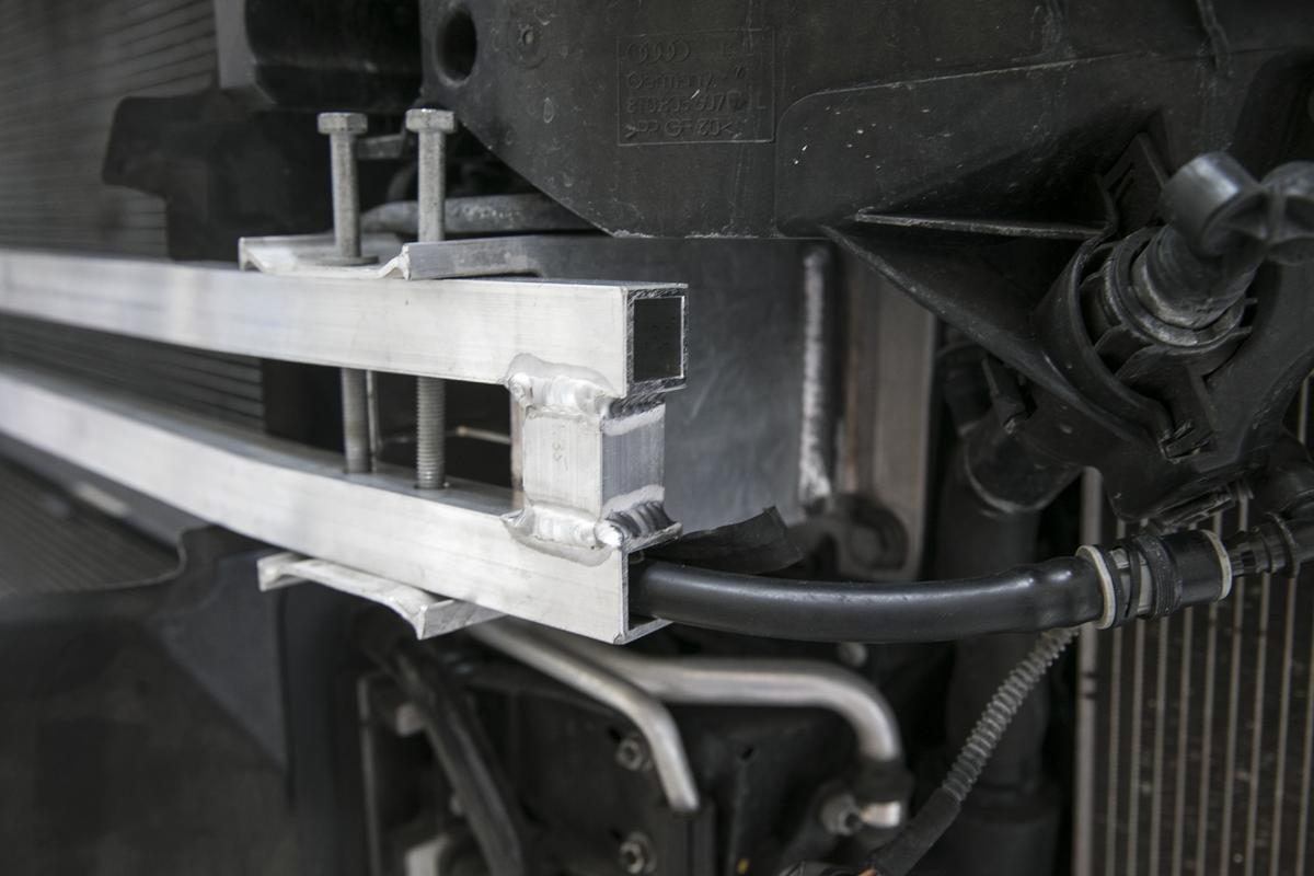
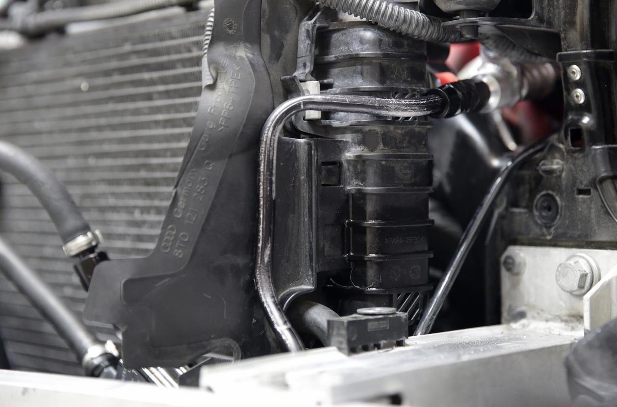
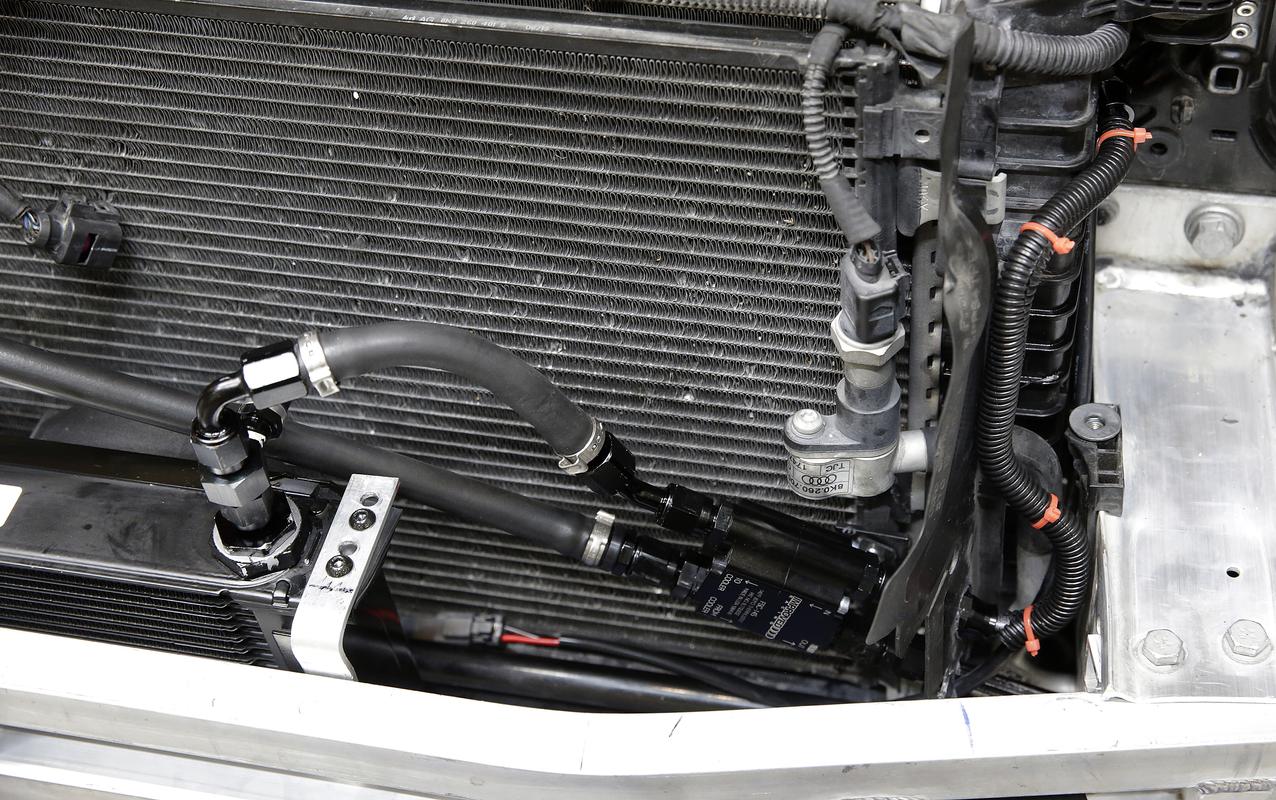
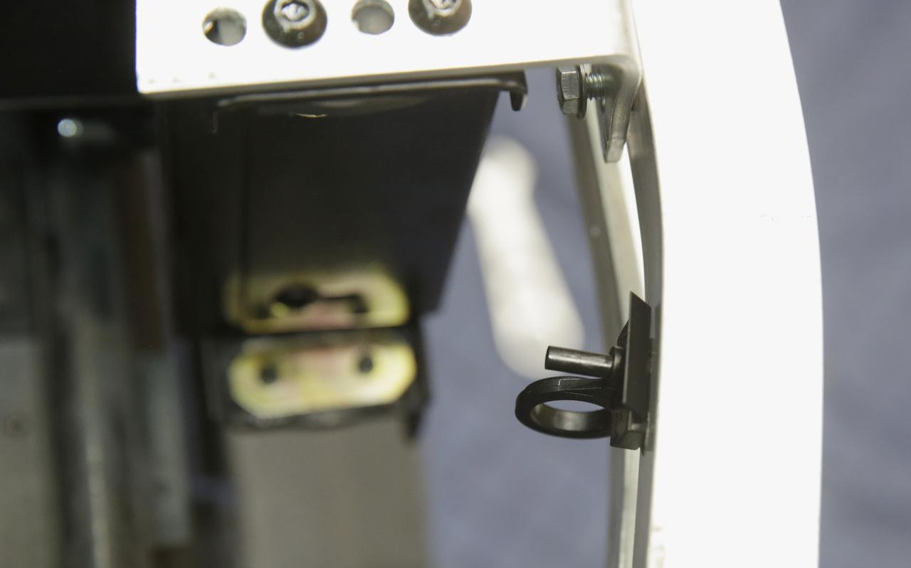
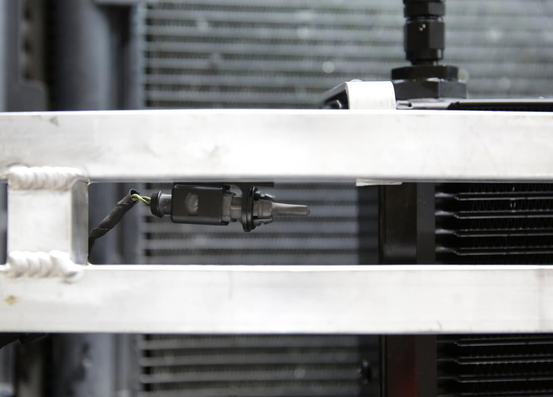
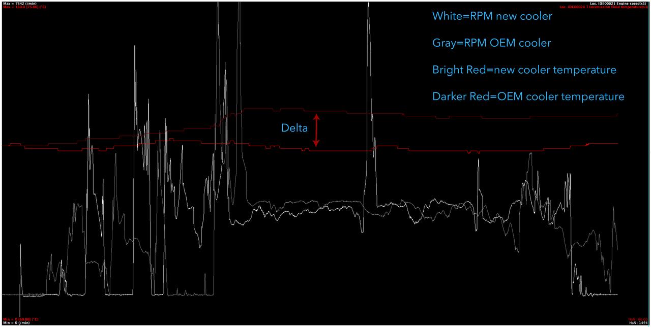
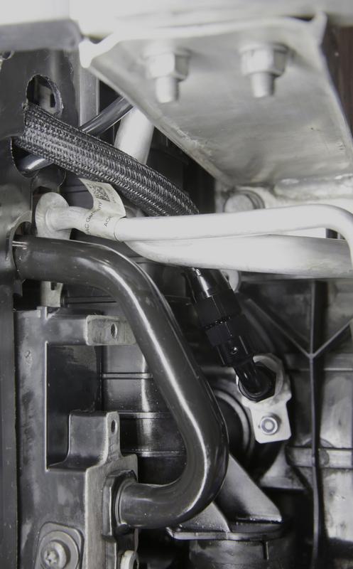
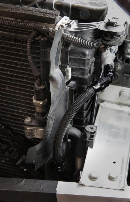
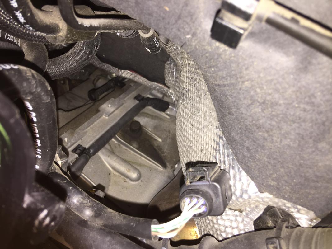
The picture below is the top of the transmission. The black cap in the center of the image is the vent and the car’s firewall is the out of focus portion in the right side of the frame. The discoloration on top of the transmission is ATF fluid that bubbled out during some testing runs.

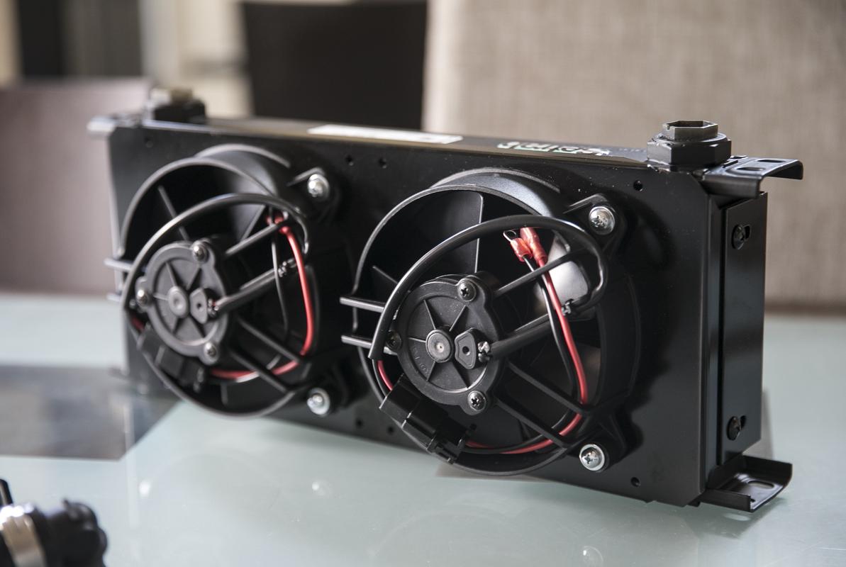
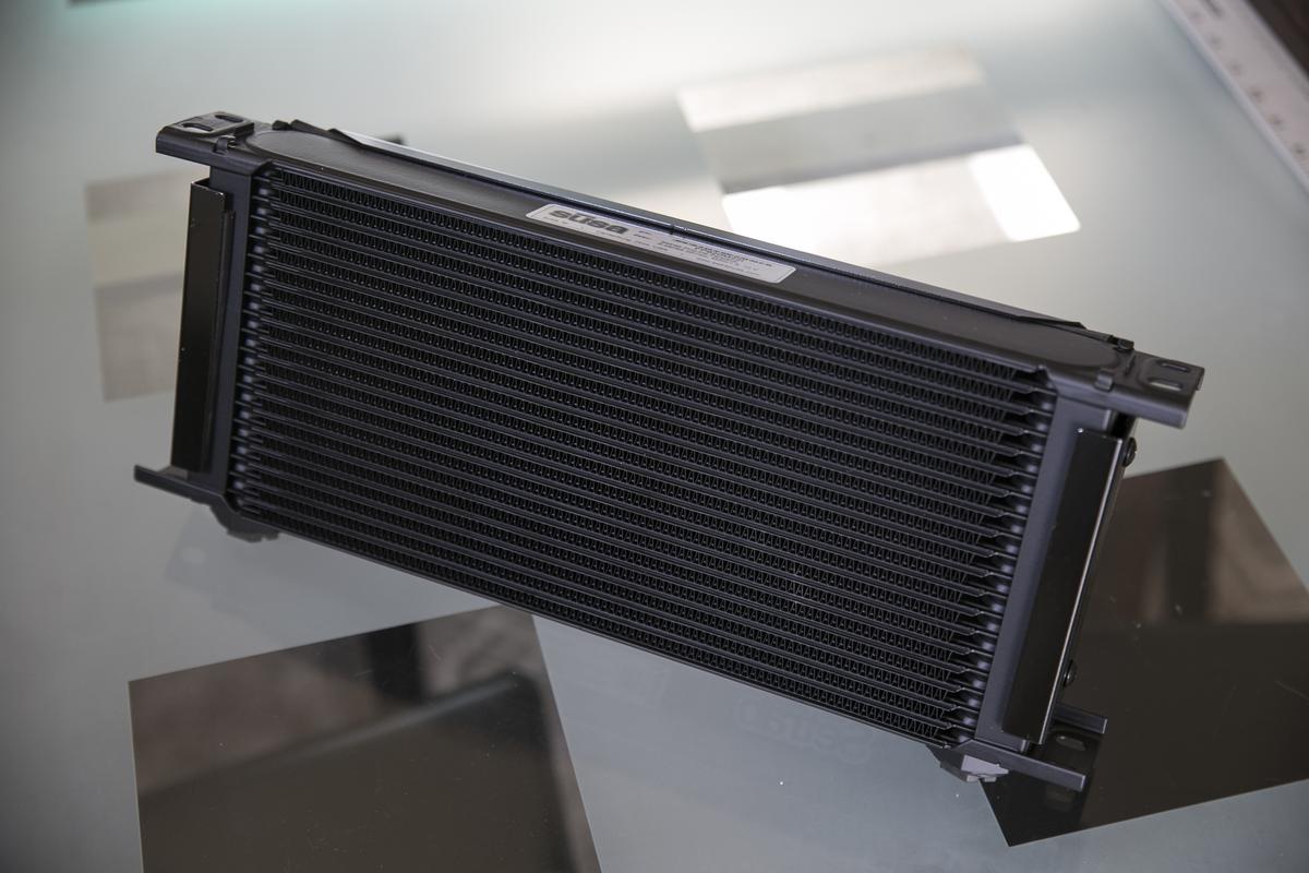
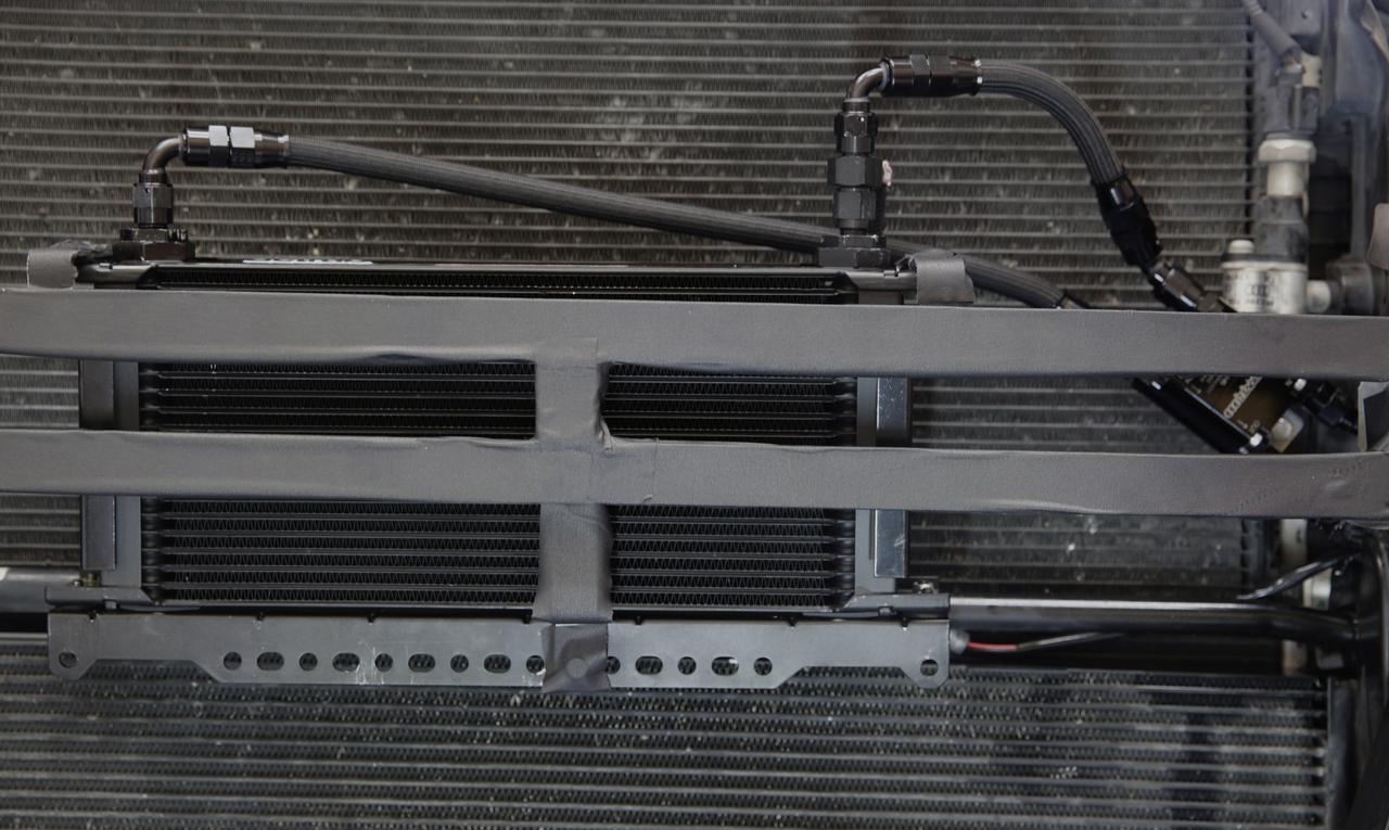
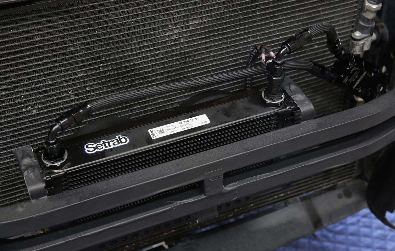
On the catch can thing…I may end up doing something later on. I just finished a thermostat design which is being whittled up out of billet aluminum as we speak. In theory, it’ll help our cars run cooler overall and bring the auxiliary radiators fully online sooner. Need to test it out on my car first of course. If it works, I may add catch cans to remove some of the volatiles and water. I already change my oil every 5K and it’ll be necessary to do so when running at overall lower temps. I also have another bolt-on affair in the works to improve heat exchange via the OEM radiator. It’ll also be cross platform compatible on all 4 and 5 series (A4/S4, A5/S5/RS5).

CARBON CLEANING IS REAL.

Busy morning. Drove over to the local dyno, JMS Racing, here in San Antonio. The dyno is well maintained and super consistent. I took the opportunity to get a good baseline before I start making changes. Just a few iPhone photos, I was using the big cameras to shoot video.

Strapping her down…

OEM intakes.

And now what you’re all waiting for. Numbers. I made three runs, hot and humid here as always. The OEM airboxes have K&N drop-in filters and I’ve not cleaned them. I’m guessing I have about 8K miles on them. Plugs were changed at 36K miles, oil change about 2K miles ago, carbon cleaning was done last fall so it’s probably been six months, have to go back and look. Tire pressure was what I always run, 42f, 38r. I run this pressure daily so I test at this pressure. I only raise or lower it when I go to the drag strip.

Interestingly, the last run made more power than the first as the car was most likely fully up to temperature and the ECU released the Kraken. Stage 1 JHM tune, exhaust is the AWE Touring. (Get to it already!)

I made almost 20hp at the wheels with just carbon cleaning. I had around 50K miles when I cleaned, probably 52K? I’m at 58K currently. That’s a power gain you can actually feel.

I have the dynojet files and I’ll post them up with comparisons to past runs on the same dyno but for now, I have an iPhone shot with all three runs along with my highest, pre-carbon cleaning run which is the 346hp run. Run #3 was 362.97 but I’m rounding up to 363. Deal with it. :slight_smile:

As I said earlier, I did shoot some video but I have to shoot “part deux” in the coming weeks. Haven’t decided if I’ll make this a separate video or not.

And now for the really good news. George installed new LED lighting and even upgraded his fans. And sitting in the corner was all of the new Dynojet software and hardware! What does this mean? It means I’ll be able to get torque readings in the future. Right now the plan is to make one more run on the current software to keep things consistent. But moving forward, I’ll have access to hp and torque curves. And the shop is about five miles from my house as the crow flies. No more 2.5 hour drives to Austin to use a busted-up dyno. I told him I’d come over on a Saturday morning and help him install it. I was that excited.

Even though we’ll be going to new software, I’m hoping it won’t be too far off the old numbers. Even so, we’ll know the delta and can extrapolate from there. He’s a pure tuner through and through so it’s incredibly important his dyno is consistent.

So there you have it. Bring on JHM stage 2!

AWE is out and ready to be sold if anyone is interested. I have it listed in the for sale section. I am willing to separate the downpipes from the rest of the exhaust. With the resonated downpipes, it’s called the Touring and with the rear section, it’s called the Track (uses OEM downpipes).

Resonated downpipes

Track exhaust


First start with the JHM exhaust! Opinions and review coming, just need to spend some time with it and let it break in as well.
[video=youtube_share;TpJ502A3bVY]https://youtu.be/TpJ502A3bVY[/video]

As promised a few graphs comparing various runs all done on the same dyno, same operator, same software.

Gratuitous waiting on dyno pic.

First graph is where I started vs. today (well, pre-JHM exhaust). You’ve come a long way baby. Lower graph is OEM ECU. Only “power” mod on the car is the AWE exhaust. The plugs have 20K more miles on them than the first dyno run.

This is my best run pre and post carbon cleaning. Both JHM stage 1, both with the OEM airboxes, K&N drop-in filters and the AWE exhaust. I take that back…I threw in an Eventuri run as well which was also with the JHM Stage 1.

These are the three latest, post carbon cleaning runs in order from first to last run (3 total).

All three of the post carbon cleaning runs together on one graph.

Let me know if you want to see anything else. I can mix and match at will.

[video=youtube_share;TpJ502A3bVY]https://youtu.be/TpJ502A3bVY[/video]

This is sort of a PSA post and others may know about it. I thought there was some discussion a while back but I have too much sh*t in my brain to remember. Anyway…while I was installing the new exhaust I decided to adjust my dampers to full hard. I’d been unhappy with their general lack of ability to dampen the springs effectively. They’ve been on the car for, I’m guessing, 50,000 miles. Seems reasonable they need a rebuild.

Anyway…I shot the last exhaust video driving around with them fully cranked. Ride was less than stellar and the car was all over the place. Not happy, I jacked the car up and adjusted all for corners, going to full soft first, then back up to full hard, then down two clicks. I thought I’d be back to where I was prior at best.

Completely wrong assumption.

They feel “new” to put it mildly, like they do not need rebuilding. Can’t explain it but I think when you keep them at a single adjustment point over time, the shim stacks can become misaligned. Cranking them from one end of the spectrum to the other then backing off to your desired setting realigns them. The latter I knew but I’m quite surprised the shim stacks can get misaligned like that. Maybe big hits do it. Dunno. All I know is I now get that perfect amount of damping where everything is perfectly controlled. One dip then level. Prior I’d get maybe two to three undulations on some bigger dip-type bumps.

If you feel your dampers have faded a bit, try doing something similar before giving up on them. I’ll most likely do this every few thousand miles or at least every oil change.

This has been, without a doubt, one of the strangest days ever. It’s been a string of falling dominos, failures, things going wrong all day long without pause. Worked a massively long day, had a brand new dryer delivered only to discover it was broken, had a technician come out to check my internet only to have the power go out as soon as he stepped in the door, a bunch of failures at work, and a big storm hit this evening while my car was outside, including hail, falling trees, you name it. It was the latest incident in a long string of incidents all day long. Was really bizarre. It was almost like you could see the bad karma in the air. Duck!

The final straw came in the form of an email I read late tonight after finally leaving the office. Jorge, from JMS Tuning, wrote to tell me the dyno broke. I’m not kidding. Now I KNOW this is going to scream “conspiracy!” so I’m posting the actual email screen grab just so everyone knows it’s legitimate. I have no idea how long it’ll take him to get it up and running but I would guess he’ll install the new software and hardware while he’s at it.

With that said, I’m not going to wait any longer to update the tune (put it off a week). We’ll just have to assume the JHM exhaust does what they say it does. The next dyno session will have to be the addition of the full stage 2 software. My apologies. It’s deeply disappointing and ever so slightly ironic. Just shaking my head at all of this.

Latest exhaust video with higher quality audio.
[video=youtube_share;tMqMGIMvbS4]https://youtu.be/tMqMGIMvbS4[/video]

Our inner city speed limit is 65mph and I never exceed that. Ever. [facepalm]

With that said, in comfort, with the valves closed, it’s very quiet, almost silent until 80mph when there’s a slight uptick in the upper frequencies meaning you can start to hear the exhaust pulses a bit more when at neutral throttle but it’s very subtle. Similar to the AWE Touring setup. Even with the valves open, there’s a small sweet spot where it’s actually, decently, quiet even at around 80-85mph. Any throttle tip-in quickly changes that and the exhaust emphasizes the lower frequencies in-cabin.

We have lots of hills here and as such, the throttle is used quite a bit to maintain speed so generally, on the highway, I have the exhaust valves closed.

Going to do a full writeup here soon. Was hoping to accomplish this with new dyno numbers but we know how that went.

Going to get to the meat of it right away. I went to the dyno this morning for more testing. Not ideal since it’s now hotter out and I didn’t get to test the two exhausts back to back with no other changes but not so fast…I may indeed have done just that.

Here’s a comparison graph, all on the same dyno. Not bad!
-Least hp is OEM ECU/TCU with AWE Touring exhaust and K&N drop-in filters
-The middle one is JHM Stage 1 tune with the same exhaust and filters
-The top one is Stage 2 with the JHM exhaust and the same filters.

Here’s a comparison between my last dyno session with the AWE and today’s session with the JHM. This’ll explain why I like this dyno and it’s operator even though I cannot get torque readings (yet!). It’s super consistent. Two different days, two different temps yet the curves are almost spot-on. I eeked out a few more hp but before you cry foul, there’s more to the story.

Lastly, all four runs from today. With each run, the hp would climb. This is not due to tire pressure but due to the ECU adjusting. More on that later.

I know what you’re all thinking; with 2.0 and the new exhaust, I should have made more hp. And I agree to a point. To be blunt, I was hoping the exhaust made a good deal more hp across the rev range. I certainly haven’t lost any.

I have a few theories. First, it was indeed about 10 degrees hotter today. I have to look up my DA but I let my Dragy run on the way to the dyno to get those numbers…looking them up and…it’s 3145. That was about the time I left the house. It was about 80 degrees by the time we made our first run and humidity was less than first thing in the morning so it might be a wash or my DA may have gone up slightly.

Second, .my carbon cleaning runs earlier this month may have been with stage 2 and I didn’t realize it. I’d been running the TCU beta which does require changes on the ECU side for compatibility purposes. Maybe I already had the hp. Considering that, stage 2 definitely makes more hp. I’ll try and clarify that. Jake, feel free to chime in.

Third, you’ll notice I make more power with each run. We were tempted to go for a fifth run but I’m paying by the hour and I don’t want to overdo it. There was no real cool-down between runs. Between runs 1 and 2, he hopped out and hooked up the wideband which took all of 20 seconds. Car left running. In between other runs, I’d simply swap out what I was logging on the VCDS and we’d make another pull. It’s not tires and Jorge basically said the ECU is still adapting and adding timing to figure out what the limits are. I’ve had the tune for two days so maybe, just maybe, the ECU needs a bit more time to fully let loose.

On the exhaust. It’s really quite amazing to me that the two graphs are almost spot-on (JHM vs AWE). I’m a bit gutted by it but I’m also thinking that down the line, as more mods become available, it’ll make a larger difference moving forward. Besides, it sounds completely bad-ass.

I have to say, my butt dyno says the car is faster. It’s obvious just merging onto the highway. There’s a difference. It’s obvious when I pull to redline or come out of a corner hard in 2nd gear and the car just lunges forward with quite a bit more acceleration.

On top of all of that, stage 2 really is about the TCU tune and on that front, I have zero complaints. Does everything it should have done from the factory. Better launch, a real manual mode, crisper, quicker shifts, a more aggressive S mode and a D mode that’s actually drivable. That’s worth the price of admission alone. I have a feeling there’s actually more to be had but we’ll see what they come up with.

I believe I’m still on a beta that they’re now testing with various other model years since I have a 2013, same as the JHM car.

Edit: Will try to have a video up of the dyno session late tonight or tomorrow.

At drag strip despite the 93 degree temps. Going to let the sun start to go down and hope the ambient temp drops a bit. Came out here to use the car scale and of course that’s broken!

And another Audi arrived! RS3

Ok first run, 12.4 @114 according to track. Dragy? 110mph.

- - - Updated - - -

RS3 ran an 11 flat.

Edit: Here’s my other time slip. I only made two runs but the DA’s actually got worse after the sun went down and everyone started running slower. Mustang that beat me was in the right lane trapping 118mp. I’m sure they’re 300 to 400 pounds lighter. If I’d nailed the light, and not red lighted, I actually would have beat him which would have been great.

Stage 1 added 25 wheel hp, stage 2 is probably another 20 wheel. I think all the car magazines use a 1ft. rollout adjustment which can improve your time significantly by up to .3 seconds. They may also use a DA correction factor. https://www.caranddriver.com/features/a18202575/the-importance-of-rollout/ I guess I could deep stage next time and eliminate some of that. I also need to go much, much softer on my suspension. I don’t think it’s helping my times as I’m three clicks out from full hard in the rear right now. My first runs ever at the track, pre-tune, I think I was trapping 108mph at the same track? The exhaust is probably 10 pounds heavier than the AWE too so I haven’t lost weight, LOL.

It was so damn hot last night. If you look at the DA number on the top of the Dragy run, it’s 3809 feet, 90 degrees out and the humidity was through the roof (80+% from what I can remember) yet I’m trapping 114 with 1/2 tank of gas. That tells me I’m making more hp than my last visit out there which, btw was also post-carbon cleaning (but pre-stage 2) on a much cooler evening.

If you go to Drag Times and use their DA correction calculator, that produces an 11.852 @119.9 mph. I used the stock/mildly modified n/a engine figures. Given I have a cat-back exhaust and drop-in filters, I’d say I qualify for that.

The track is now NHRA certified so I know their timing is accurate. Just wish that damn scale had been working as I could calculate hp with that figure. I’m about 205lbs and I’m guessing the car weighs 4100 pounds with half a tank of gas. But that’s just a guess.

I did loose out to a new Mustang, last race. No idea what he had but he specifically lined up against me so he must have watched my first run. I ended up red lighting (barely) and he ran a 12.1 but was gaining on me HARD at the end of the run. I may have gone through the traps first by a whisker. I think he trapped at like 118 or 119? Sounded like full header/exhaust and intake at the very least, with drag radials. I also need to take a hard look at shift points. I did a quick test last night and I can indeed get launch assist when in M.

On a side note the RS3, with bolt-ons and a tune ran a 11.0 and then later a 12.0 but I think he flubbed the launch, not sure. The owner said he had been running APR’s software but dumped them when his car left him without power in the middle of the highway. Said his dash lit up like a Christmas tree at some point after getting the APR tune and I’m guessing he switched tunes which solved the problem. Didn’t talk to him in-depth about it but I’m going to guess he’s on the forums, maybe even here on Audizine. There’s a GTR with full bolt ons and E85, he was running mid 10’s. So much easier with turbocharged cars!!!

In terms of testing your car here Ben, not a bad idea at all! I’d wait until fall when things cool down. The hotter it gets, the more timing is being pulled and the less hp you’ll make. You could go stage 2 and then have your car carbon cleaned. Anxious to see how dirty your valves are right now. That’ll be great info to have. Heck, you could drive over here the night before or something and stay at my place. That way we could be at the dyno in the morning first thing. It’s about five miles from my house. Would take some planning but it’s doable. I’m sure the new dyno software will be up and running come fall too so we’ll have torque figures.

Honestly, we need more people testing stage 1 or 2 at the drag strip in different (hopefully better) conditions. But summer is here unfortunately and I’ll just have to be patient and wait for October to roll around. I’m super happy with the way the car drives now and it’s powerful enough to be slightly evil. It can catch you out and that’s quite a big change from when it was stock. It’s just killer on the back roads through the hills which is what this car is designed for.

I just did a DA correction using the actual weather data for the track and my ET came out to 11.98@118mph. The DA was 3016.

[QUOTE=BuyTheWarranty;13716584]That’s a great 60 foot time, I think the same as JHMs record 11.94 run. The revised launch is obviously killer.

Question for you. Even with the bad DA (3800), you got a great 60 foot time and trapped 114mph, which is almost identical to JHMs stats, why still a half second difference? I must be missing something (My fastest trap speed has been 111mph with a DA of 1900). Conversely, if you had lower temps you’d be under 12 I’m positive.

Edit - just noticed on all your Dragy runs on stage 1 prior to June (not sure if you had TCU or not) but your trap speed was 109-112mph (same as me). On stage 2, you’re trapping 114-115.XX so almost a 3mph improvement so most likely there is a 20wheel horsepower gain coupled with the better launch.[/QUOTE]

According to JHM, they set that time on stage 1, probably in much cooler conditions although I’ve heard they ran an 11.9 in 85 degree temps. If they were going off of the Dragy trap speed, and it’s as off as mine is, then perhaps they are trapping even higher. Dunno. They had a 1.76 60ft. time but pulled a higher g force than I did. All I can think is due to the heat, I should have trapped even faster and heat has a greater effect on ET vs. trap speed. Could be my shift points too. I don’t know what theirs were. I just left it in S last night. I was going to do a run in M but pride got the better of me and I didn’t want to loose to a stang with a less than optimal shift, LOL.

Maybe their car is just faster from the factory. It happens! I’m sure they have a bunch of technicians which look over the car regularly and I’m assuming they’re running fresh plugs, injectors, things like that. Here’s one of their 11.9 runs…

I should really, really be in the mid 1.6 range for the 60ft. I need to bring my jack so I can adjust my suspension but I’d just have to leave all that stuff sitting out when I make my runs and that’s not a good idea here. Yeah the car feels really solid on launch, no issues. I think it still may be loosing rpm off the line but I didn’t log last night, just wanted to concentrate on driving. Seems to maybe fall a little flat in 4th but that could be placebo from watching a Mustang gain on me, LOL.

Passengers, please get ready for liftoff. On the rollers at JMS Motorsports for a dyno run.

New dyno video.
[video=youtube_share;K3t-cmQkLmQ]https://youtu.be/K3t-cmQkLmQ[/video]

Since I’m copying/pasting over from another forum, the in between questions and responses are lost, Here’s JHM’s response to the dyne numbers:
"The fact that it made the same power with our exhaust on a 10* hotter day is huge! Specially since its already in the hotter end of the weather! (going from 50* to 60* will lose less power than 80* to 90* temp) What cannot be calculated on a dyno is our ECU protections the come into play with hotter IAT and EGTs etc… While the dyno can correct for the atmosphere it certainly can’t change the fact that the car is running in a much hotter environment where protection modes come into play and timing starts to get pulled out etc…

Another thing to keep in mind that all of our software is developed on the street, not a dyno. A dyno will not and cannot produce real-world conditions (airflow from small fans will not replicate actual airflow in real life for an example. Stick your hand out the window while driving 80mph and then put your hand in front of a dyno fan). So if you compare the two cars with the same mods and all variables the same EXCEPT a Street Tune vs Dyno Tune, and they made the same HP numbers on a Dyno, if they were to race side by side the Street Tune will be faster because it was"

It was 101 F on the way home last night and I definitely felt it affected the performance of the car. I can’t even imagine driving in 122 F.

Speaking of high temps, here’s my latest little project, new crash bar with 1/4 the surface area of the OEM bar allowing more flow to the heat exchangers. So if you add something like an air to fluid transmission cooler, you’ll still come out ahead and won’t be reducing airflow to the radiator. It’s aluminum tool so super light and will have a modular bracket system. Will have first test fit next week when I get back from Cali. Will of course be powdercoated so it’s not highly visible behind the grille. Will most likely work on all 4 and 5 series.

Air pump hose relocation kit installation video.
[video=youtube_share;RsXW_XInP4s]https://youtu.be/RsXW_XInP4s[/video]

I’ll have more info on the high flow crash bar tomorrow along with photos of it installed along with, hopefully, the auxiliary thermostat I’ve whipped up.

Ok…long day. Lots of taking stuff apart, measuring, etc…Crash bar prototype #1 is installed. Tons of clearance front and back, I may move the entire thing forward two inches. It really a massive difference over the OEM crash bar and cover. This one isn’t powder coated but I did cover it with black gaffer’s tape just to see how visible it is. With the tape, it’s pretty much invisible. I’ll take pics in the daylight tomorrow to show what it’ll look like when it’s black.

There are a few knick knacks that have to be removed from the old crash bar including the horns and ambient air temp sensor. Everything’s pretty easy to remove and transfer over. To keep the cost down, you may be required to drill a few holes. It’s aluminum so it’s fairly easy.

The cover is easy to remove from the grille but there are wires for the various electrical components in the bumper which ran through a piece of foam. There should be an easy work around.

A few photos.

Here’s the crash bar cover laid on top of the new crash bar. You can see just how much airflow that thing blocked.

With the front fascia installed.


With the carrier cover removed and looking down, the white sticker is on the oil cooler. There’s about 4.5" of space aft and 2.5" forward of the bar depending on where you measure. Should be enough room for a good-sized transmission cooler with a fan pack.

With black tape. It’ll be pretty much invisible once it’s powder coated black.

As promised, more photos in daylight of the new cross bar installed. We’re going to call it the RMR cross bar.

OEM crash bar and cover

Details…

I took a spin to the prototype shop doing the work (that’s literally what they do, prototype stuff from robots to parts for Toyota) as I decided I wanted to make a few changes. First, we’re going to move the bar forward at least an inch on the sides and try a compound curve to move the exposed portion of the bar forward about two inches. It’ll add to the cost but it’ll also give me a good deal of clearance behind the bar for mounting a large heat exchanger with a fan.

Second, need to move a section of the bar over a few mm for tow hook port access and we’ll most likely add an inch of overall length on each side.

The third issue was solved by my desire to move the bar forward. The connecting fluid line between the headlight washers runs through the OEM crash bar. With the current bar, the bolts take up all the space and there’s no room to run the line through the bar. An additional bit of stock is being added to the back of the bar which’ll push the bar forward an inch and the bolts will run through it, not the man beam. The washer fluid line will then be able to run through the bar uninhibited.

I should have prototype #2 by next Monday.

I did do quite a bit of hoofing it around town today, mixed between highway and city driving. Was in the mid-90’s, no issues. This bar is not going to lower the temperatures beyond what the map-controlled thermostat will allow but with that said, I was generally running between 202 and 208 Fahrenheit with no big jumps in temps despite pushing the car when possible. I’m sure it’ll make a difference on a track.

[QUOTE=JamesRS5;13739433]Michel, looking at the OE bar, it looks to have a shear point at each end where the aluminium flattens out from box section to flat plate (correct me if I’m wrong, just going off what I can see in your picture). I assume this is to prevent the chassis legs being pulled together in a front impact which would make a small front impact into a much larger repair or even possible write-off if the chassis legs are bent.

If this is the case then it may be worth notching or slotting one side of the box section at each end on your design to allow for this shear to occur. The OE bar has the channel pressed into it to give longitudinal strength against flexing which you have plenty of with the box section but you may have a bit too much strength in a front end impact?[/QUOTE]

I was going to address this in another post altogether but the OEM crash bar is designed to handle a 5 mph impact (head on) and nothing more. It’s not torsional, not load bearing, like a strut bar would be to twisting/bending compression forces. It merely tries to contain some force from a frontal impact running front to back, parallel to the ground and chassis. The mounting holes are slotted on one side (for production tolerances) on the OEM bar and there’s a big gap pretty much all the way around the OEM bar when it’s mounted and snug. The upper and lower portions of the box section it attaches to are pinched down when you tighten the bolts. The box section is then bolted to the front subframe extrusions on either side. The box section is what you unbolt when putting the car into the service position. The space between those two marks is pretty small. If you were to rear end a smart car, it’d still cover a majority of the width of the front end. I suppose if you hit a light pole, dead center, that could come into effect.

I’ll have to take a hard look at it but I don’t think there’s a shear point on the OEM bar. That’s merely the manufacturing jig bend point. You can see marks from being gripped then formed in several places on the OEM bar. I can take some pics and post up.

And with all that said, this is designed to be an “off road” racing bar. I make no claims it’ll protect as well in the event of a front end impact. The best protection against that scenario is to not rear end someone! It is rather strong though. You could easily club a baby seal with it and it wouldn’t leave a mark on the bar. The bar is currently series 6061 grade aluminum which works well for everything we’re doing and is very strong. We may have to switch to a five series if we can’t get the compound bend and it necessitates a ton of additional welding. I have to look at this from a production/cost standpoint too as no one is going to buy a crash bar for $1,000. Every additional weld or bend adds man hour costs. Luckily the welder is uber talented with aluminum (and other materials) having worked for Bell Intercoolers for years.

Another change is we’re adding another vertical brace on the other side of the bolt holes and changing the curve at that juncture to bring the whole bar forward. The car steered and handled curves just as precisely (or imprecisely depending on your view of the RS5!) as before. There was no change in handling.

Weight wise they’re about the same but I’ll get a weight on the new one when it’s done. Without this bar, surprisingly, there’s very little room for an additional, proper heat exchanger setup. There may be one setup which’ll work and I may offer that as a street-based kit that’ll still cool far better than the OEM transmission cooler, especially in traffic, but it would not be optimal for autocross or track days like a bigger core would be, especially if someone throws a supercharger on the car. This bar will give you additional space for that heat exchanger too while still allowing for more direct airflow to the radiator.

The auxiliary thermostat has hit a snag. I’ll post up details on that tonight. Maybe some of you will have some ideas!

More updates. My main goal is to have the most compact components with no compromise/loss in performance. I managed to whittle the auxiliary thermostat down considerably, move the hose barbs in so they sit flush and shorten the barb length. This should fit perfectly now.

Keeping with the compact theme, the new transmission thermostat is in and its a hair over 2" long. Super compact and will be easy to mount on the driver’s side of the engine bay. It also In addition, there’s a thermal switch for the two fans mounted on the back side of the core. This will be a boon for anyone driving in town as even at a standstill, with the fans going, it’s like driving at 50mph. They flow that much air. The lines will be hard lines with a section of soft line for isolation of vibration and movement, just like the factory lines. The transmission line adapters are also designed, just waiting to check off on their design. You’ll be able to access fittings with minimal effort, one being located at the top of the engine and one at the bottom but is plainly visible with the splash guard removed.


I have to say, the high airflow crash bar seems to be making a difference in keeping the temps on the low end of things. Any rise in temps fall rapidly. It’s been brutally hot here lately, pretty much 98 degrees daily. I leave work late, round 10pm and it’s still in the 90’s. Can’t wait to get the transmission cooler and auxiliary thermostat in, think it’ll be a game changer for consistent performance.

Couple of updates. We were able to do a compound bend with 6061 so we’ll be moving forward with this design. I’ll have a few more photos tomorrow but essentially what you see below is the new profile. It’ll move the furthest forward point of the bar up to 2" and give lots of clearance between it and the a/c condenser. Why so much space? The fan packs for the heat exchanger core.

Speaking of the heat exchanger core, the new one is in. It’s wider but not as tall and after speaking with the in-house engineer, it should actually outperform the original spec and is capable of handling more BTU’s. Two Spal fans on the back will move a serious amount of air if you’re standing still. This is the time when the mechatronic/ATF fluid really seems to heat up in daily driving situations.

Lastly, the latest version of my air pump hose relocation kit. Moved to a one-piece single heat shield with abrasion resistance built in. Will handle 1200 degrees all on it’s own without a separate shield over the base shield. It’s actually a bit more expensive to do it this way (higher grade material) but it’s cleaner. Even though I’ll never actually see them! All the other components are rated to 300 degrees just like the factory fittings. The blue tape is there just for labeling purposes.

I’m going to have a bunch of free time over the next few weeks so the transmission cooler setup will evolve very quickly.

Few more pics of the front crash bar showing the compound curve. This’ll allow for a large “straight” section of the tubing for mounting heat exchangers easily. Should have a finished version early next week and assuming I’m in good enough physical condition, I should have the new transmission heat exchanger mounted.

There will be a second layer of bar stock (front to back) which’ll contain the slotted bolt holes. The front portion will be free and open in order to run the headlight washer hose through it just like OEM.


So while I’m waiting on various parts to be made, and given the fact I’m stuck at home and have some down time, boredom set in and I decided I’d join the 21st century and ceramic coat my car. Waxing is getting old even with the new stuff that seems to last for a longer period of time these days. I’m pretty much a novice when it comes to paint correction and I’ve never ceramic coated a vehicle.

After a bit of a chat with JamesRS5, I selected a number of products based on his recommendations to do this from the ground up. The effort began in earnest Tuesday morning with a decontamination/strip wash to remove any protectants followed by prodigious use of a synthetic clay sponge over every inch of the RS5’s painted bodywork. I had to wait for Amazon to deliver the correcting compound later that day and I also had a big brown box arriving on a big brown truck Friday with a finishing polish, a prep cleaner and the ceramic coating kit. I pretty much knew this was either going to go really well or be a horrible mistake.

For the correcting compound, I purchased an 8oz. bottle of Jescar. Wednesday afternoon I began the correction process with Jescar correcting compound and a bunch of Meguiar’s microfiber cutting discs (DMC6). I finished with the correcting compound around 5pm Thursday. Yes, it really took that long but the results were pretty stunning. The Misano red paint is really something special and usually all it takes for it to pop is a cleaning. But this is on a whole different level. And the Jescar finishes so well I almost thought about NOT doing a final polish. It was that good. Here’s a quick iPhone pic.

With that out of the way I took a break for a few hours and while I was icing my wounded parts, UPS delivered my package a day early. That never happens.

Anyway, I resided to starting up again on Friday morning but watching a few videos motivated me to head back out into the garage and start the polishing process. I used Sonax Perfect Finish and I managed to get everything done by about midnight with more time spent using Gyeon Prep to degrease everything in preparation for the ceramic coating. This was a much easier step in terms of time and effort and honestly, the difference was negligible between the Jescar and the polish. I could see a difference and I’m sure it’ll contribute to the final look after being coated. I may not have used the right pad but the finish already had so much depth and clarity, it would have been hard to make another leap like that with the finishing polish.

So far so good, no real issues and everything’s going to plan. We’ll see how the ceramic coating turns out. I went with Gyeon Syncro which is a two material process. The first is the Mohs which will require two to three layers. The second part is Skin which is a hydrophobic coating applied after the Mohs. I’m a bit worried due to the heat and humidity and I’ll most likely have to break it up into even smaller pieces to avoid any removal issues. I’lll report back when I’m done!

And a few days later…

It’s done. I will most likely never, ever ever do this again myself. It just takes too damn long and I could probably come up with a solid plan for world peace in the same amount of time. I’ll have to do the math but I don’t think, in the end, any time will be saved in not having to wax the vehicle over the next two years. Granted, I’m not an expert at this and I was a wounded warrior so I probably accomplished each phase a bit (ok a lot) slower than a pro.

With that said…I started on Wednesday and didn’t really finish til this morning (Sunday!). This morning was a coat of Cure since I’ll be driving the car come Tuesday. I actually took the car out today. I had a nightmare I’d be t-boned pulling out of my driveway by a rust bucket but I digress…

Overall the car looks great, very “glassy”. I’ll have to really examine it more in the sun but to me, it doesn’t have as much depth as a good synthetic wax. Unsure if this is because a wax may cause an overall halo effect or what. I’m in no way displeased with the overall shine and appearance though. It’s just effing tedious!

So I do actually have one issue with ceramic coating (other than the time it takes). When they say it’ll magnify every flaw, “they” mean it. I didn’t really understand until I looked over the car while applying the Skin portion. When applying the skin, every flaw is painfully exposed until you wipe off the excess. In addition, the Mohs portion seems to white over any nick you have in the paint. So where the “edges” of the small nick were probably red, they’re now white. And very visible where they once weren’t. This may very well be user error on my part and would not bet against that notion.

While most of the car looks fantastic, the front splitter (shocker) just doesn’t look good at all. I’ll most likely have it repainted in the near future and possibly the hood too. Bottom line, I think ceramic coating makes a lot of sense on a new or newish car but not one with 50K miles on the odometer and original paint.

There’s still a lot of maintenance for ceramic coatings including regular washings so contaminants don’t build up. So now I’ve added a foam cannon to the arsenal and will have to use TWO different soaps to wash the car. Really? The good news is there’s no rain in the forecast for the foreseeable future. The bad news is there’s no rain in the forecast for the foreseeable future so I can’t sit there and laugh at the amazing hydrophobic qualities of the finish. It really is that slick. Can’t wash the car for seven days. That gives me a week to try and figure out what shampoo I can use that won’t completely destroy the ceramic coating. Such a rabbit hole.

Sadly, I haven’t had a chance to take any photos. I have yet to treat the trim as I want the ceramic coating to cure fully. I’ll have a bit more time tomorrow (well, today) to take some photos. I was hanging out at a swank hotel (Hotel Emma, look it up, amazing bar!) most of today with a friend from out of town and the car did break a few necks as crowds walked by.

Ok two quick pics as I have to run. It was literally high noon when I shot these and it was just an opportune moment where I found a good background (or lack thereof) when running between machine shops today. Not the best light to show off ceramic coating.

Work continues on the cross bar and transmission heat exchanger. Cross bar prototype #2 looks to be the one as we’ve managed to nail the bends and make it even stronger as well. Additional bracing is being installed and as I mentioned before, the whole bar will move forward by two inches. Doesn’t sound like much but with this crash bar, folks will be able to run multiple, very large heat exchangers, whether it be for oil, transmission fluid, intercoolers for forced induction, etc…and it’ll fit any B8. The amount of increased airflow as is, with just the bar, is substantial. The car has been running quite cool despite the 100 degree temps here.

I’ve decided to go with a matte bed liner type coating. It’ll be impervious to rocks and won’t chip. It’ll be done by a professional metal coating facility using an industrial grade process. I’m not messing around with these.

I’ve also finished 99% of the wiring harness design which will be plug and play. No cutting or splicing necessary and all connections are weatherproof. I’ll need to have everything fully installed to finish that last percent. I’ll take pics tomorrow morning, too late to pull out the camera and take photos.

A few pics of the new design being welded up. Should be done by Tuesday or Wednesday. I’ll take more photos when it’s complete. I most likely won’t have time to install it until the weekend as I’m back to the day job.

Thank you for the kind words! And yes, temp stability will really help with consistency and it’ll take a bit of the load off of the radiator and coolant.

The check is in the mail! Seriously, great idea. Just need to figure out which coating to get. Trying to get one that’s fairly smooth and doesn’t have a lot of texture to reflect light.

It really is. It’s just stinking hot and the light is really harsh in Texas. Light in Florida is far better.

Here are a few shots of me building the wiring harness. I have to modify the original harness coming off of the fan pack to a universal sealed plug that’ll work with the rest. The plugs are also smaller so they’ll fit through smaller openings and be easier to install overall. Trying for long continuous runs with the least amount of connections possible to minimize points of weakness.

Original harness.

New. Much neater.

It’s like an erector set.

The relay will make it plug and play. It’s quite small, inline 40A fuse. I’ll swap the one pictured out for a waterproof version.

Most of the gear. It’s tedious but will be worth it in the end.

I’m picking up the new cross bar before work and will have that swapped in this weekend so I can finalize everything. The only holdup now is the adapters for the OEM lines. I had a brilliant idea at 3am on Saturday night which required changes to one of the adapters. But having issues sourcing an already in production wire retaining clip so I may have to go back to plan A. Once that’s done, everything will be ready to go. I’m also doing provisional patents on everything as I’ve put a ton of time and financial resources into this stuff.

Once the bumper is off I’ll test fit the auxiliary thermostat as well which is a separate component from the transmission cooler. Was really hoping to have the new crash bar two weeks ago due to all my downtime.

A carbon roof is way out of my league although I’ll ask around if there are any composite specialists in the area. With all the military stuff here it’s likely.

The latest cross bar version is now in my possession. I’ll install it on Sunday and finalize all of the hard lines and the wiring harness. Shouldn’t be much longer!

In the first pic, it’s sitting on top of the OEM crash bar off of my car with two bolts slotted through both the new and the old. We slotted the new just in case there are production tolerances.

This one shows the additional rear clearance that’ll be gained. If we followed the rear of the crash bar, there’s less than 4" in between the back of the bar and the a/c condenser. Not enough to run anything but a core. No fans which isn’t ideal for any car that sees street duty.

And lastly, absconded and in my trunk!

So moving on to v3 of the crash bar. It was “almost” perfect but it needs one small adjustment. We went a bit too far out in the corners but figured out we’ll actually be able to cut out the compound curve altogether and simplify the construction a bit. Should have the new one for a test fit on Friday.

I pretty much finalized the transmission cooler placement which honestly is very difficult, especially with the fan pack. But no compromises! The homelink transmitter creates a real issue and eliminates a lot of potential space. With the bumper off it looks like there’s a ton of real estate but it’s not the case with the bumper on. Everything else on the crash bar was spot-on so this should all come to fruition very soon.

I’ll talk more about placement later, have to run to the day job!

I woke up at the crack of dawn this morning to test crash bar #3 and give the car its first wash since ceramic coating.

Crash bar #3 is a success! Fitment is pretty much spot-on where I wanted it. It’ll now support the grille as well as fulfill all the other needs. I’ll be doing rivet bolts so everything will transfer over easily. We have two horns on either side which are riveted to the OEM bar. They’re aluminum rivets so you can just drill them out and pull the horns off. With the rivet bolts, there’s no need for another bolt and it’s a cleaner, simpler, one tool installation. The headlight washer fluid cross-hose now feeds through the top bar unrestricted, just like the original and the ambient air temp sensor will have it’s own little hole on the bottom for it’s bracket. More on that in another post.

A few bad pics via smartphone, had to go to work today so time was critical. I can easily jack the car up and take the bumper off in half an hour. Kinda crazy how I can almost do it in my sleep now.

Almost SIX INCHES of clearance between the back of the brace and the a/c condenser.

The homelink sensor provided a major obstacle in mounting a large heat exchanger. I thought about relocation but the bracket it snaps into doesn’t look easy to remove. I didn’t explore fully so it may be an option in the future.

Ignore the brackets, they’re just for mockup/spacing and will be redone by the machine shop.

I should have everything bolted up and working within two weeks. Excited as the temps here have been 100+ for weeks on end.

Almost forgot to give my ceramic coating impressions!

Have to say, it made the process of washing the car MUCH easier and less time consuming. I think I cut the overall wash time in half. The water beading/running off the car was simply amazing and drying was a new experience. One wipe of a super plush microfiber towel and all the water is gone. Nothing is left behind. No photos but I’ll be at cars and coffee in Austin tomorrow and will take pics then.

Cars and coffee on Sunday in Austin. Got to meet one of my YouTube fans who just picked up a Sepang RS5. So that was kind of surreal for both of us. Hot as hell out there. Winter can’t come soon enough. Key is getting there early before everyone parks around you, that way you can long lens it!

After C&C, I went over to Asher Audi’s place to flash his car and we did a small photo shoot.

Latest (and last!) version of the cross bar is done. The design is finalized. This is the bare bar before having mounting hardware installed and coated. She’s good to go!

The final part of the transmission cooler equation is done. Took a herculean effort and I switched engineering firms to get this produced correctly and quickly. The body is one piece and converts the Audi fluid line fittings to standard AN or even NPT if needed. Being one piece, it eliminates a point of failure. Scalable and I can size it to whatever fluid line needs an adapter. Audi vehicles use the male portion in multiple spots for things like transmission, oil and coolant lines. Patent pending!

I’ll finish up the transmission cooler this weekend and will be laboring in the heat on labor day. Have a cold one and think of me. It should be another 100 degree day.

I used Audi part number 8K0807113G as a guide which is the crash bar for the RS5 but fits other Audis.
Which holes were drilled differently? The four mounting holes for the bolts or for the accessories?
https://parts.audidominion.com/p/Audi_2013_RS5-Base-Coupe-42L-V8-AT/Bumper-Impact-Bar/48597895/8K0807113G.html
The Audi site lists the bar as being compatible with the following:
Audi A4 2.0L A/T Quattro Avant Wagon 2009, 2010
Audi A4 2.0L A/T Quattro Base Sedan 2009, 2010
Audi A4 2.0L CVT FWD Base Sedan 2009, 2010
Audi A4 2.0L M/T Quattro Base Sedan 2009, 2010
Audi A4 3.2L V6 A/T Quattro Base Sedan 2009
Audi A4 3.2L V6 M/T Quattro Base Sedan 2009
Audi A5 2.0L A/T Quattro Base Coupe 2010, 2011, 2012
Audi A5 2.0L A/T Quattro Cabriolet Convertible 2010, 2011, 2012
Audi A5 2.0L CVT FWD Cabriolet Convertible 2010, 2011, 2012
Audi A5 2.0L M/T Quattro Base Coupe 2010, 2011, 2012
Audi A5 3.2L V6 A/T Quattro Base Coupe 2008, 2009, 2010
Audi A5 3.2L V6 M/T Quattro Base Coupe 2008, 2009, 2010
Audi RS5 4.2L V8 A/T Base Convertible 2013
Audi RS5 4.2L V8 A/T Base Coupe 2013, 2014, 2015
Audi RS5 4.2L V8 A/T Cabriolet Convertible 2014, 2015
Audi S4 3.0L V6 A/T Base Sedan 2010
Audi S4 3.0L V6 M/T Base Sedan 2010
Audi S5 3.0L V6 A/T Cabriolet Convertible 2010, 2011, 2012

Now there’s also 8K0807113F which fits the 2013+ S4/S5 but Pete has a 3.0T S5 (what year Pete?) and theoretically the bar I made should not have fit but it does. He’s also using the RS5 conversion front nose so maybe that’s it? I did slot the main mounting holes, maybe that allows them to fit. I’ll know more when I get the S4 over and test fit the bar on it.

I’ve been busy to say the least and haven’t had time to update anything. The transmission cooler setup has been on the car and I’ve been logging daily and just making sure everything’s kosher, no leaks, no issues, everything working as it should. The preliminary results are really promising to say the least.

I’ll be ripping everything out yet again tomorrow and installing the final version of the ATF lines. I’d decided early on to run hard lines but that isn’t going to work out for a couple of reasons and may even be detrimental. So I upgraded to a new type of flexible PTFE hose with a 1" bend radius (very important) and a protective sheath. Costs $10 a foot so it isn’t cheap but it’ll be well worth it for installation ease. Trying to make that part as easy as possible and this hose will go a long way towards achieving that.

But in the meantime, I did actually bend hard lines to go from the OEM line/adapter to the in ports on the thermostat housing. Can’t run full hard lines as the thermostat is rigidly mounted to a different surface from the cooler. It’s all in the details.

So this was the first installation with some hard line, some soft. I didn’t have all the fittings necessary to run flexible lines post thermostat but for mockup, it was fine. I’d ordered black aluminum lines which turned out to be somewhat of a mistake as the bending tool and the straightening tool just removed parts of the finish.

Here’s the hard line on the top side, very complex bend as it’s a tight fit. Also a real pain to reproduce and install, hence the switch to a flexible line.

I pressure test every line with adapters up to 120psi. The fittings are rated up to 250psi.

Lower and upper adapters installed, lower has a cap to protect the threads. Upper is fully installed.

I switched to half hard, half flexible lines and finished the installation. I didn’t have all the hose end fasteners that I wanted so this too was a temporary setup until I could order more.


The thermo-switch which activates the fans on one of the adapters.

I also worked on the mounting setup to make everything as clean as possible. Everything will mount on the back of the bar with one screw/washer. No nuts, less to drop and again, makes installation easier. Rivet nuts are used everywhere for mounting.

The air temp bracket will mount like OEM. No zip ties here!


The horns were a bit tricky, takes some rotating and repositioning of the bracket but they now have a spot and don’t interfere with anything. Rigidly mounted just like OEM, again with rivet nuts. OEM actually rivets them in but they’re soft aluminum and easy to drill out. Notice the headlight washer hose is now routed through the bottom tube on the crash bar just like OEM.

Lastly, all new fittings and the new flex line. You’re looking at about $300 worth of parts. All of this will go on tomorrow and I’ll update the thread with new photos.

As for performance, everything’s still in the early stages but the concept has been proven over decades of motorsports development and the core is more than large enough to handle the RS5. I’m running about 20 degrees Celsius cooler than through the OEM trans cooler. I’ve not been able to get the ATF fluid to a temperature where the fans would kick on yet. The thermostat is fully open by 74 degrees Celsius (165F) and the fans don’t come on until you hit 180. The thermostat begins to crack open at 62C (145F) so I’m typically seeing stable temps between 68C and 74C. This is not with hard core spirited driving over long distances. This is in-town, highway, with occasional bursts of acceleration. Baby steps but this thing should really perform amazingly at the track, drag strip and autocross as well as the back roads for weekend warriors. With the thermo load more stable, it should also help keep the car’s performance at the optimal level and end thermal management interventions on the transmission side. You’re also lessening the burden on the radiator and cooling system as it’s no longer having to remove heat from the transmission. For those in colder climates, the thermostat’s specs can be easily changed by swapping in a different temp range into the housing.

In terms of heating the fluid up to operating temp, there really isn’t much difference between the integrated OEM and my fully-divorced system. I believe the clutches do a whole lot of the fluid heating. I can share logs with anyone who’d like to see them. I’ll graph a few out when I’m at work today and post those later.

Lastly, I’ve experimented with the fluid level. I’m running 18oz more ATF fluid (about half a liter) in the system due to the cooler core being that much larger than the OEM unit. I lost maybe 8-10oz of fluid out of the OEM cooler. I think most runs back into the lower line and ATF pan when you shut the engine off. One thing I’ve noticed is the transmission has become noticeably smoother in all parameters, downshifting, coming to a stop, acceleration, etc…If your gearbox feels as though it’s a bit rough, might want to check your ATF fluid levels. I’ve checked mine twice since doing the last service so I was a bit surprised by the difference. Could be a combined temp and volume factor. The PCB attached to the mechatronic is now running cooler as a result and the kit should help increase mechatronic and ATF service life. Temps can get pretty hot with the stock cooler. I’ve seen temps reach almost 150C (300 degrees) when doing a few launches back to back and hitting the back roads on a weekend.

Here are two graphs, one with the OEM cooler and one with the new cooler package, both charts are during the summer and both days are 95+ Fahrenheit. Both are hot starts (car was warm already) and the starting temps for both units were the same. The point A to point B was also the same, from my house to work which is a mix of city, access roads and highway. The delta is the difference between the two with the new cooler running at a lower operating temperature overall and maintaining it. This is a very simple one but illustrates the difference between them. If I continued driving, the OEM would continue to climb in temps.

RPM is the white line. The “higher” the peak, the higher the revs. Bright red is the new cooler, the thinner, dark red is the old.

The second is two launches, back to back, with the OEM cooler. I’ll do likewise at some point with the new cooler. The peak temperature is 95 degrees Celsius (203F) and I’ve seen much hotter. No, you wouldn’t normally do two launches back to back but I was doing some testing (stage 2 beta!) and I wanted to see how quickly temps would ramp up. Now here’s the thing…the clutch packs get quite hot and radiate/transfer heat to the fluid. It takes time for the heat to transfer to the fluid fully but you can actually see the clutch temps drop and the ATF fluid temps get higher if you’re monitoring with the VCDS. Pretty cool.

I have more logs and I’ll post them at a later date. If anyone wants the raw data of the two graphs above, just holler at me and I’ll email them to you. They’re .CSV files so you can look at them in Excel or purchase the MegaLog HD software (it’s cheap) and graph them like I have. I logged more than rpm and ATF temp parameters so you can pick and choose which ones to look at or look at them all at once.

The new lines are finished and installed. I like these far more than the hard lines and they’re super light. Really nice stuff and it’ll make installation cleaner and far, far easier for everyone else. Worth the additional cost if it saves you installation time and frustration.

A few photos of the new hoses.


Even though the hoses have a built-in protective cover, I added another woven protective sheath to both lines which run from the OEM hard lines to the thermostat. They run through tight spaces and while they don’t press up firmly against anything, better safe than sorry. Overkill is good. No zip ties on this one but I secured the sheath with ties on each end and it goes over the end of the aluminum fittings as well.

Lines installed.

You can’t get a clear shot of the shorter lines which connect the OEM hard lines to the thermostat so this is with parts removed.

I’ll be doing more testing tomorrow, driving a lot further which’ll allow me to test hot starts and cool-down times as well as hopefully get the temps up above 80C so I can see the fans doing their job. Once the car is moving at a reasonable speed, the temps drop quickly. I want to see how well the fans bring down the temps when the car isn’t moving or moving at a crawl.

Coolant temps haven’t changed at all which is as-expected. They’re controlled by the ECU adjusted thermostat. A/C works as normal so no issues there either.

More testing. This is a dual graph, one on the top which is rpm (white) and transmission fluid temp (red). With the transmission up to temperature, I accelerate to redline and then slow down to around 10-15mph before coming to a complete stop and idling with no airflow.

The bottom graph mirrors the top, same point in time for each position on the graphed line. The clutch pack temp (yellow) is telling. It’s where a majority of the heat is generated and it take some time to transfer from the clutch packs to the ATF fluid. There’s a natural latency in that heat transfer as well as with the sensors reading the temperatures.

What you notice is the fluid temperature rises a few degrees, maxes out at 80C and then cools down to 79, 78C while the car is idling. The green line is vehicle speed on the bottom graph. That’s the fans kicking in and keeping the fluid temperatures reasonable and dropping the clutch pack temp as well. Without the new cooler, the fluid temps would be at least 100 degrees Celsius (212F) if not higher. I’ve seen them much higher with the OEM cooler. IMO, it’s really the weak link and I honestly wonder why a better system wasn’t designed.

With improved cooling the ECU will always run at a lower temperature than it would with the OEM cooler. As computers get hotter, they slow down and aren’t as efficient in their operation. Same with the one inside the mechatronic.

Had I not come to a stop and continued on, the fluid temps would have stayed around 70 degrees Celsius. And yes, it’s hot out again today. Ambient temps were about 98F, or 37C. I have two more days of hot weather for testing as it looks like a big front is coming through with much needed rain.

A little video teaser, a launch with JHM stage 2 plus ripping through the hills/canyons in Mexico. I shot a ton of video on Monday along with logging data on the transmission cooler.
[video=youtube_share;DafaCWO7-YE]https://youtu.be/DafaCWO7-YE[/video]

A little video teaser, a launch with JHM stage 2 plus ripping through the hills/canyons in Mexico. I shot a ton of video on Monday along with logging data on the transmission cooler.
[video=youtube_share;DafaCWO7-YE]https://youtu.be/DafaCWO7-YE[/video]