Advice Requested - CEL's (cam position actuators & intake flaps)

Got the car up on the SUV adapters and have about 30" to the bottom of the forward frame rails. Since I plan on leaving the suspension in the car, I have to disconnect the axle/front suspension components, including the sway bar and I will be pretty close to pulling the engine.

Car up on the Quickjack with the SUV adapters:

Does anyone have any advice on how to support the engine on my platform lift so I can remove the transmission once it is out? I am sure I can figure it out, but if there are any BTDT’s that would be great.

I sspent the last few days getting the parts list together and checking prices and availability. Some parts have been ordered already and I am going over my Audi dealer quote for the rest. I still need to figure out what coolant lines I need to get, but I will do that in a second round of ordering once the engine is out and I can see what I need to do. I have used Eng92’s excellent post to help ID the parts involved.

I have to do a little garage reorganization so I can wheel the assembly out of one bay and into the other for the work, and today is a good weather day for that.

Ed

Works like a charm.
https://www.harborfreight.com/1000-lbs-capacity-hydraulic-table-cart-60438.html

You might need to modify depending on your space but it can hold 1000lbs easy. That covers both your motor and transmission.

What lift is that your currently using.

Quickjack:

ECS Quickjack

That’s from ECS, but I think even COSTCO has them (they come in 3500, 5000 and 7000 LB units.

I used the HF platform to drop my 997 engine. I already flipped the handle so it drops down away from the platform so I can slide it under to get the platform where I need it. Now I just have to figure out where to place blocks so I can get the transmission off once it’s out.

Moving right along. PS fluid and cooler detached, ground strap pulled, most coolant hoses detached (though the Bentley seems to differ on some items) and I am just about to pull the ECU’s and lay them on the engine:

I’ve got my proposal from Audi and it looks like the total bill will be about $5500 in parts and supplies which includes a $2000 IM.

I’ve been photo documenting everything and like other work I have done, I have a few tables set up and have been bagging and tagging everything. Just a ton of stuff, but the 911 looked more complicated than a human circulatory and nervous system. At the same time that engine seemed much better suited for pulling than this one, probably because almost everything requires a drop there.

997 engine fresh out:

With all the crap off ready for work to be done:

Anyway, back to work!

Ed

So I am ready to head under the car and start disconnecting there. I had posted some stuff in my UrS forum and one of the guys who has a lot of experience replied that he had fixed his flaps on his 4.2 (jury rigged but it worked). With thoughts of possibly saving $2K, I decided to dissect the IM and I was quickly disappointed.

First there was a ton of oil inside (is that normal) - I had replaced the separator about a year ago, maybe it was in there from the bad unit?:

I removed the runners, but even before I could see a missing flap and a loose flap where it shouldn’t be:

The cyl 10 flap was back down on cyl 6, the retainer was in cyl 6 and the connecting piece was in cyl 1. The front operating lever was completely disconnected and the other bank of flaps was no longer attached to the end of the IM.

Also every single flap was disconnected from the other (I assume the two separated pieces in the center should be one solid piece and not rotate separately from each other):

Finally a couple of flaps had their edges worn off:

So even if I could have pulled something off reagarding securing the flap guides to the IM, since they are no longer connected to each other it wouldn’t have made a difference.

Also, how the hell was this engine even running with plastic pieces in the throat of the chamber and all that oil and junk from whatever stuck to the flaps and walls of the IM?

Calling it a night, will be back at it tomorrow.

Ed

Keep with it Ed,

We’ve all been there. While the pill of 2k for the intake might be hard to swallow. Now you see why it’s almost always the best bet.

Oil wise. That looks a taste on the high side for oil. Not crazy, but if you already had oil in the plug well that could be part of a higher level of crank pressure getting into the intake.

That is a lot of oil.
When I disassembled my IM it contained more oil, and when ever I floored it on the highway after slow driving, it left a cloud of smoke behind.

My oil separator was defective, which is quite common.
So you might look in to replacing that.

I went a different route and just removed the entire PCV system and went ‘free vent’ on the crank case.
Last week when I vent to clean my injectors I checked my IM and it was bone dry.
I did the removal 11 months ago and have now driven +25000 km.

I had replaced it a couple of years ago, before that there were 9 years of driving and about 170,000 miles so it may just be an accumulation.

I will have to research free vent. Did it have any effect on carbonization?

Ed

I took a couple of days off from the project to let my mind breathe. I did pick up a box of parts from Audi (including the IM) but they forgot a couple of hoses. I am still waiting on FCP Euro, JHM and an eBay provider for some other parts. The timing tool and the cam girdle alignment pins are here.

So here is where we stand:

  1. No Catch can. The PCV system is pretty straightforward, I will inspect and clean
  2. The old IM is a PITA to take fully apart, I am trying to salvage the flaps for a member
  3. The wiring is disconnected and waiting for the mechanical to be the same

  1. Most of the mechanicals are disconnected. I kept sway bar links on the bar to save the cost of two bolts, yeah! I left the suspension on the car and disconnected the drive shafts (they are still attached to the transmission but will probably be coming off either before or after pulling everything). I strung up the F&R LCA’s to the top of the suspension as described in Bentley. But instead of a strap, I used jack stands to carry the weight of the suspension to prevent damage. I was surprised the LCA bushings seeming to be in such good shape, but the ball joints swung fairly easily, not sure if they should be done or not, but that will be for another day.

I need to disconnect the compressor and mark the position of the subframe on the longitudinal arms and where they mount near the transmission. I will probably do the same to the trans mount as well. I need to disconnect the main driveshaft to the rear and loosen the sleeves on the exhaust and then I will be ready to drop the engine. I am still trying to figure out the best locations for blocks of wood and how high I should make them to give me room under the engine.

Looking to do that by the end of the day.

Ed

PS: Is there a way to attach files? I want to attach a spreadsheet of parts/tools for anyone who might find it helpful when I am finished, but I cannot see how to do that. I have looked at the FAQ’s and other forum info, but I must be missing it.

When you hit reply there is a box that pops up. The one you post in. From there at the top there is a list of icons. follow those to the upload icon. Click and then load your files.

Ahhh, I was overthinking it, so the Picture Icon is really upload any file Icon. Got it.

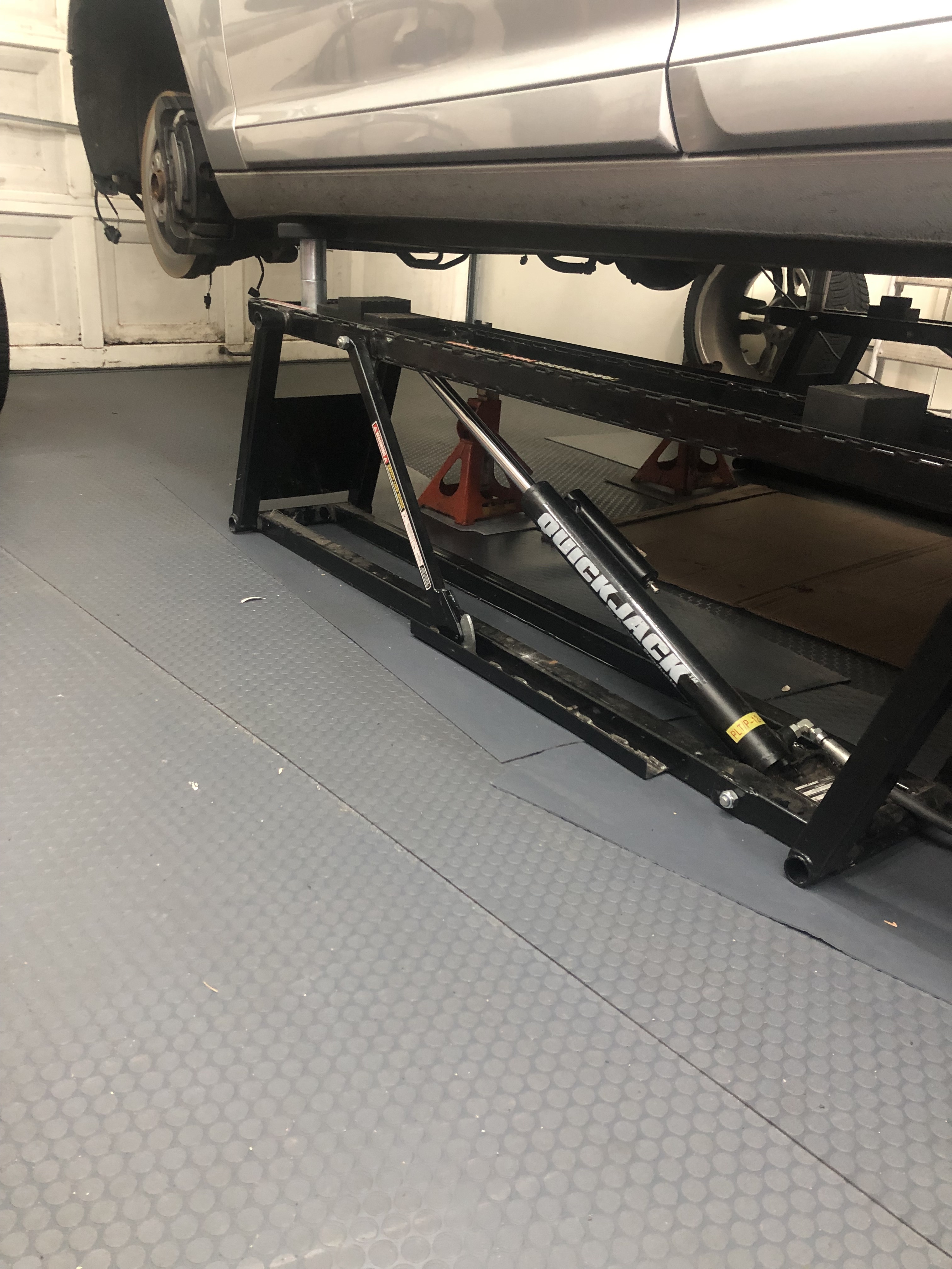
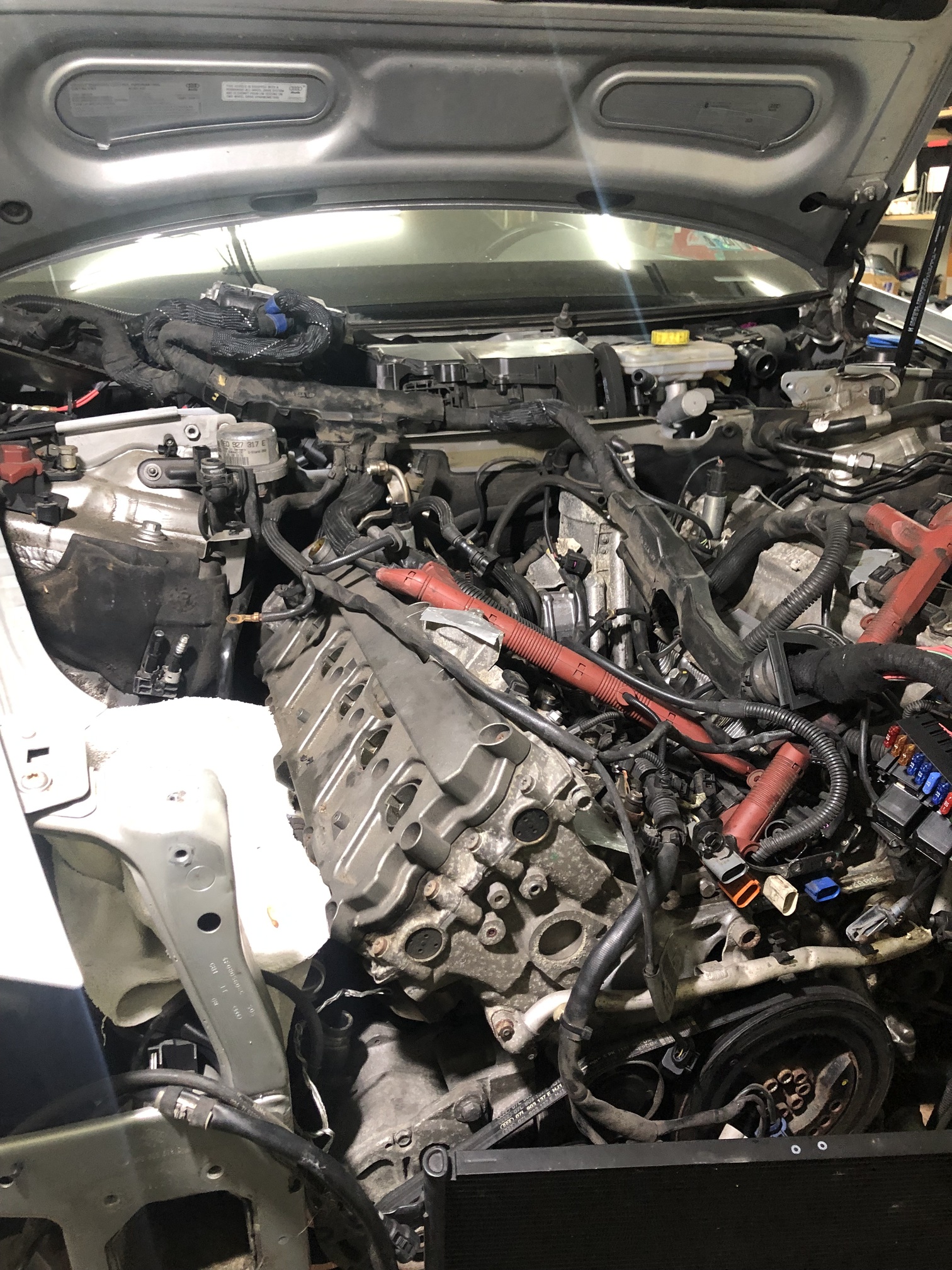
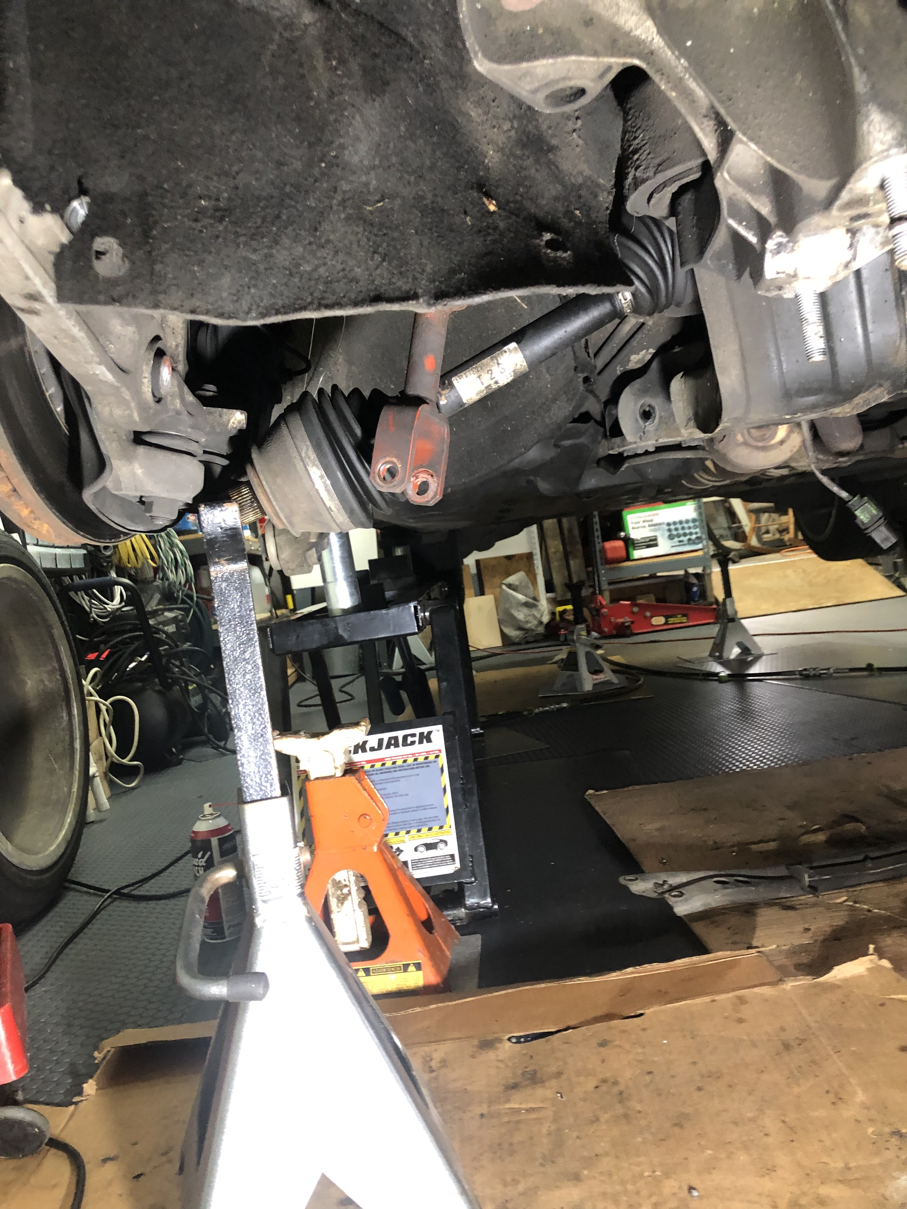
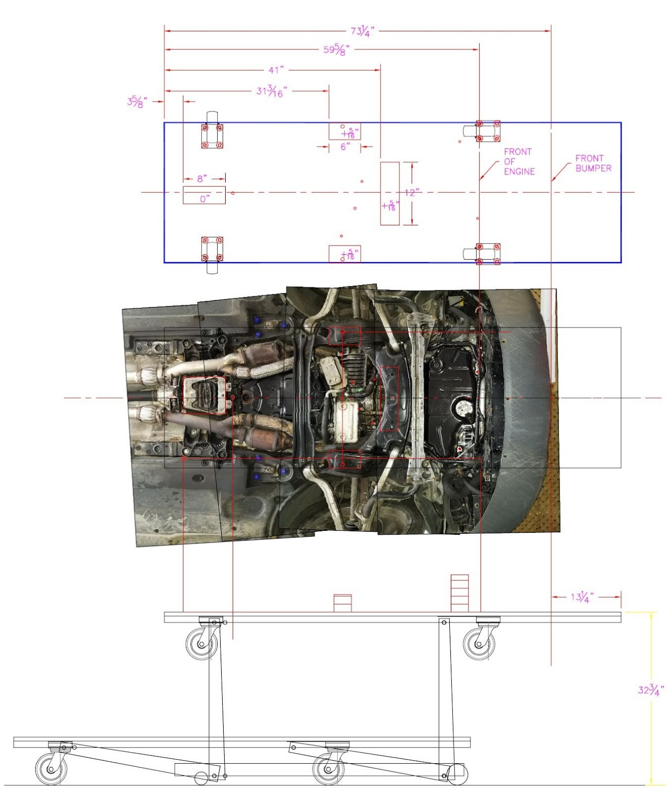
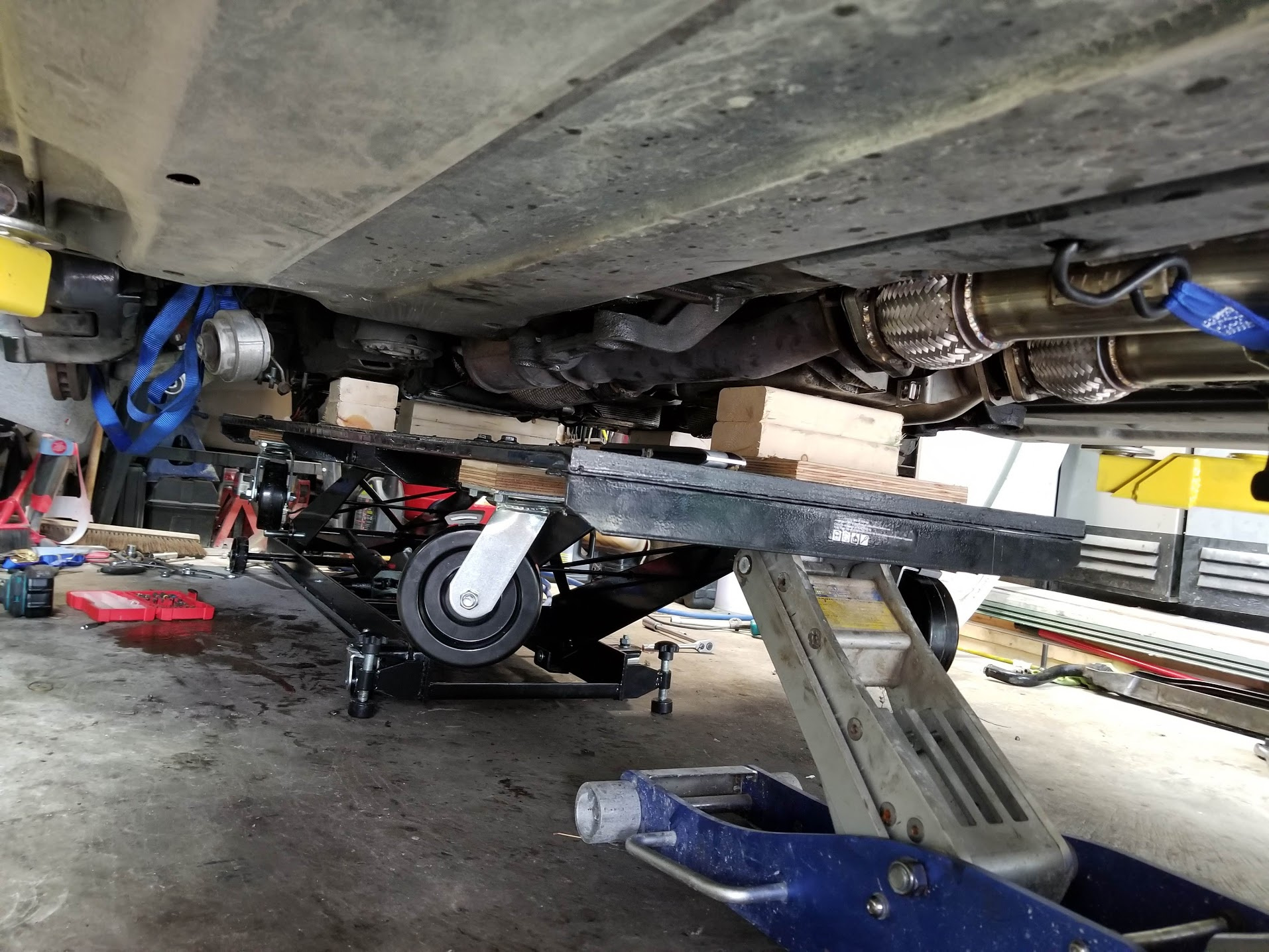
I decided to remove the axles now. The rear main axle nuts were on pretty good and I still have to whack it a bit to separate it, but that is the last thing before positioning the platform jack under the engine. It is 50 cm wide X 80 cm long, so it is about 40 cm short (120 cm from front mount hole to rear trans hole) to cover from the front engine support to the rear transmission support, but it is plenty wide to cover the mount holes left to right.

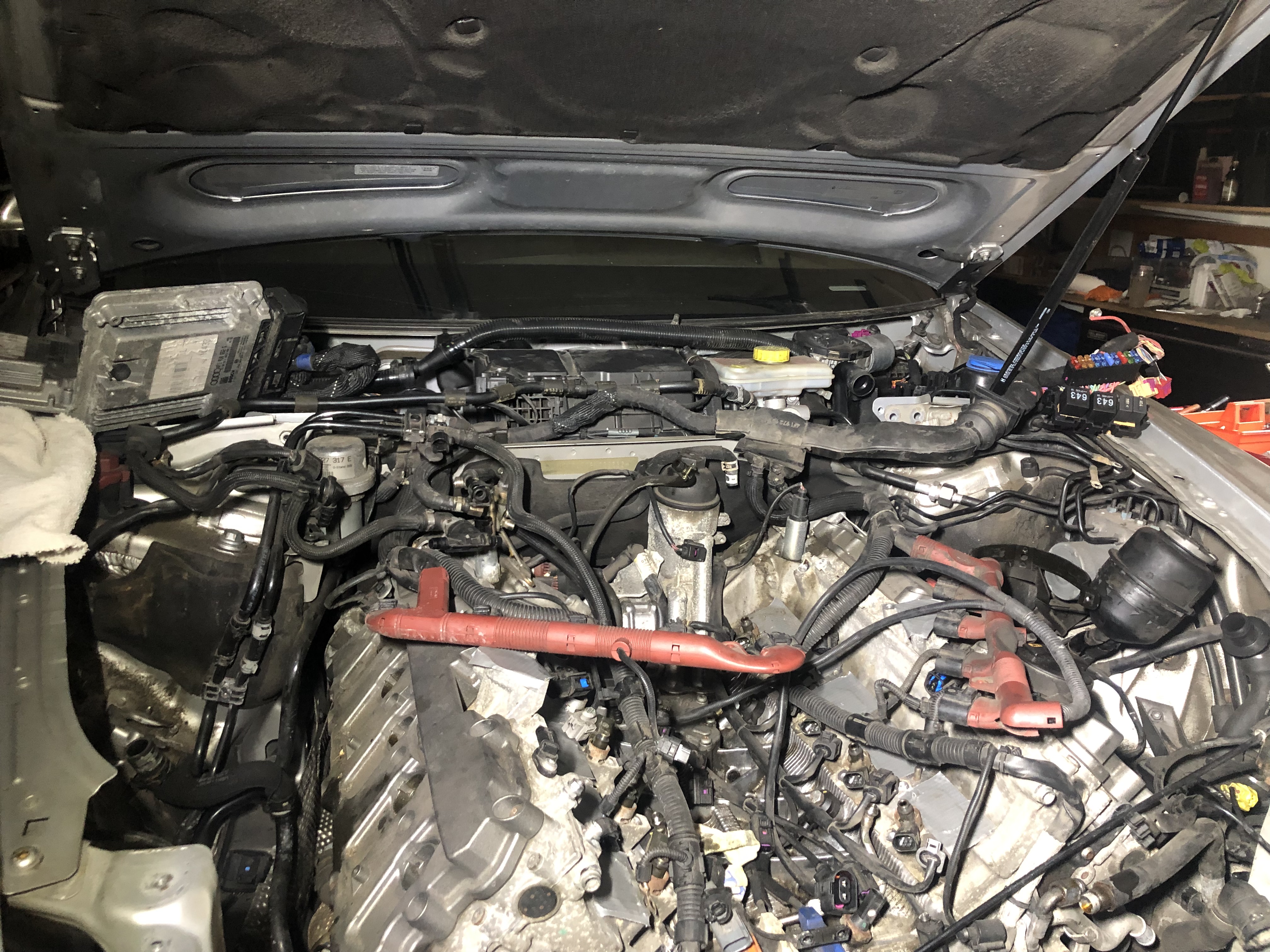
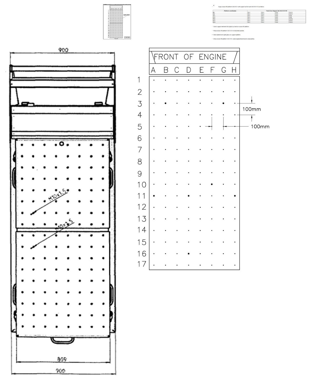
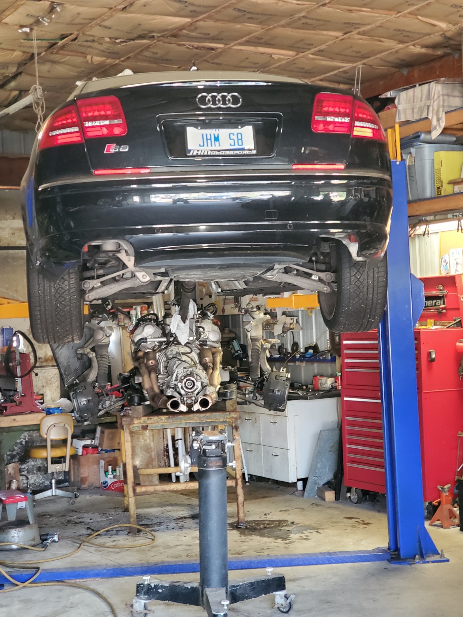
I am about ready to yank the engine but I am still wrestling with how to support it. I want to replace the motor mounts and I don’t wan’t to interfere with them. The table and support layout in the Bentley, when I map it out, doesn’t match the driver side front hole for positioning the factory tool support. It seems to jive with the holes hidden by the subframe and the front hole on the passenger side. I have not mapped out the transmission mounts yet, but they seem to match looking at my drawing (though I can’t use the rear one - not sure what to do there yet).

I have determined (I think) that the dimensions on the table pictured in the Bentley as 12cm squares. At least that seems to match up to three of the four engine holes.

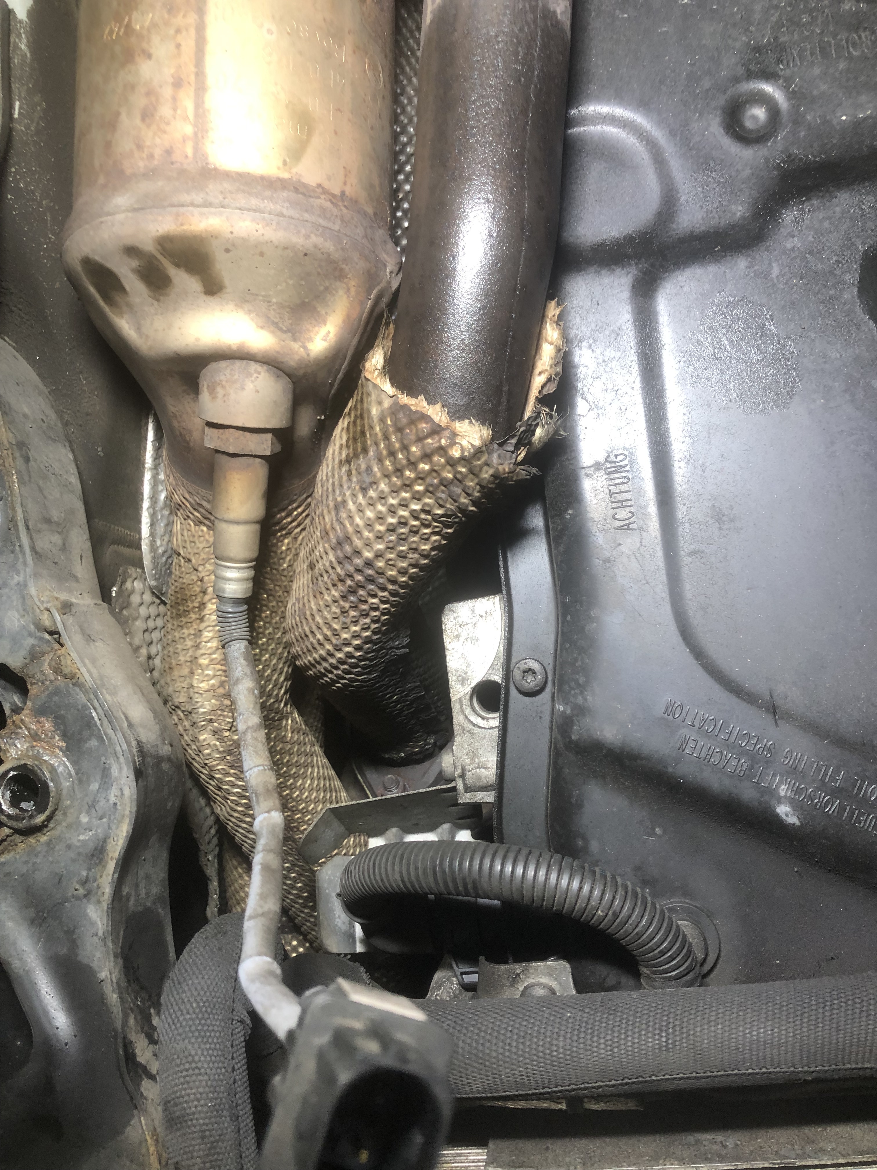
Is it possible that the Bentley is wrong? The WP assembly sits right where that support wants to be from the Bentley.

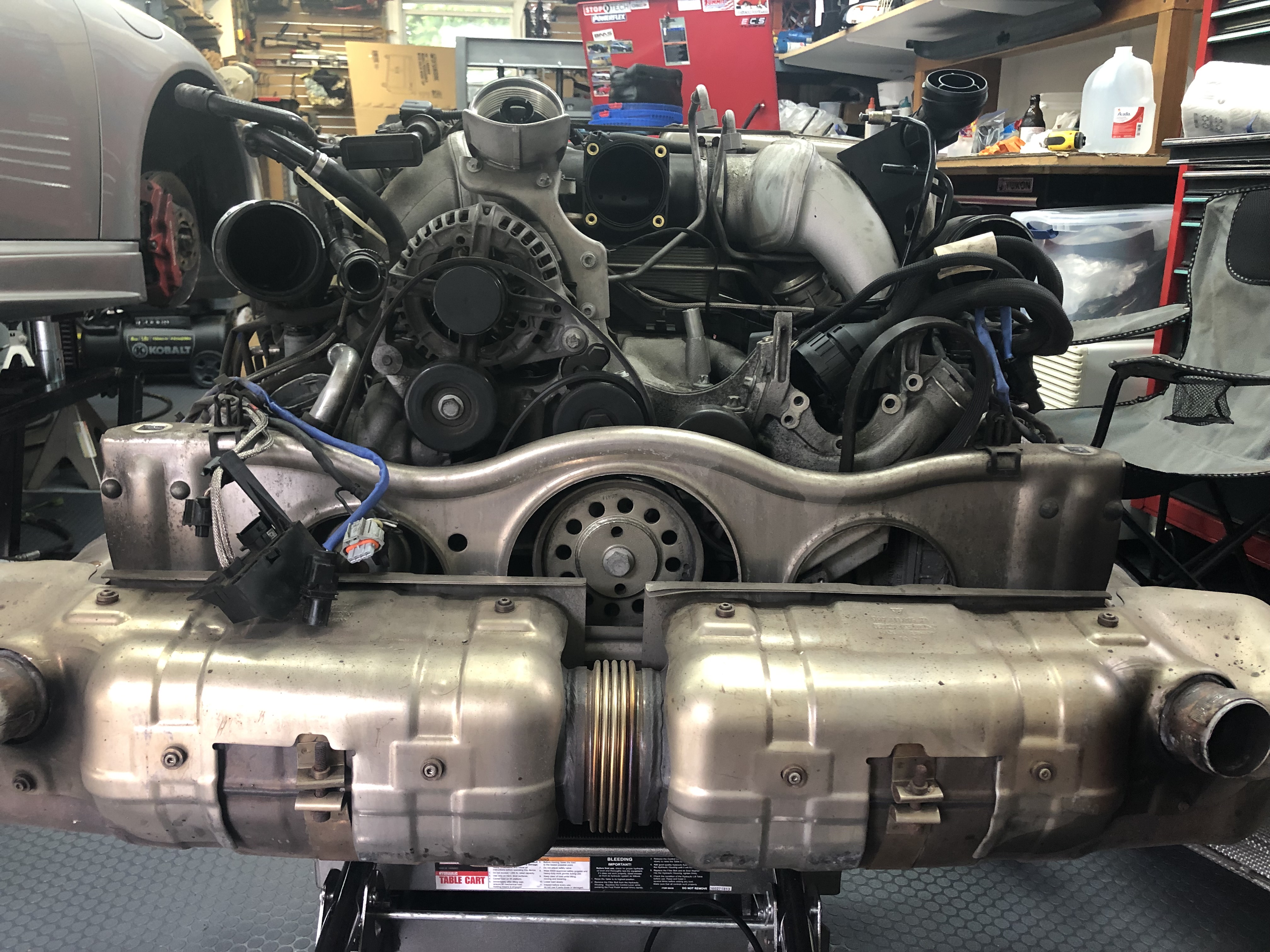
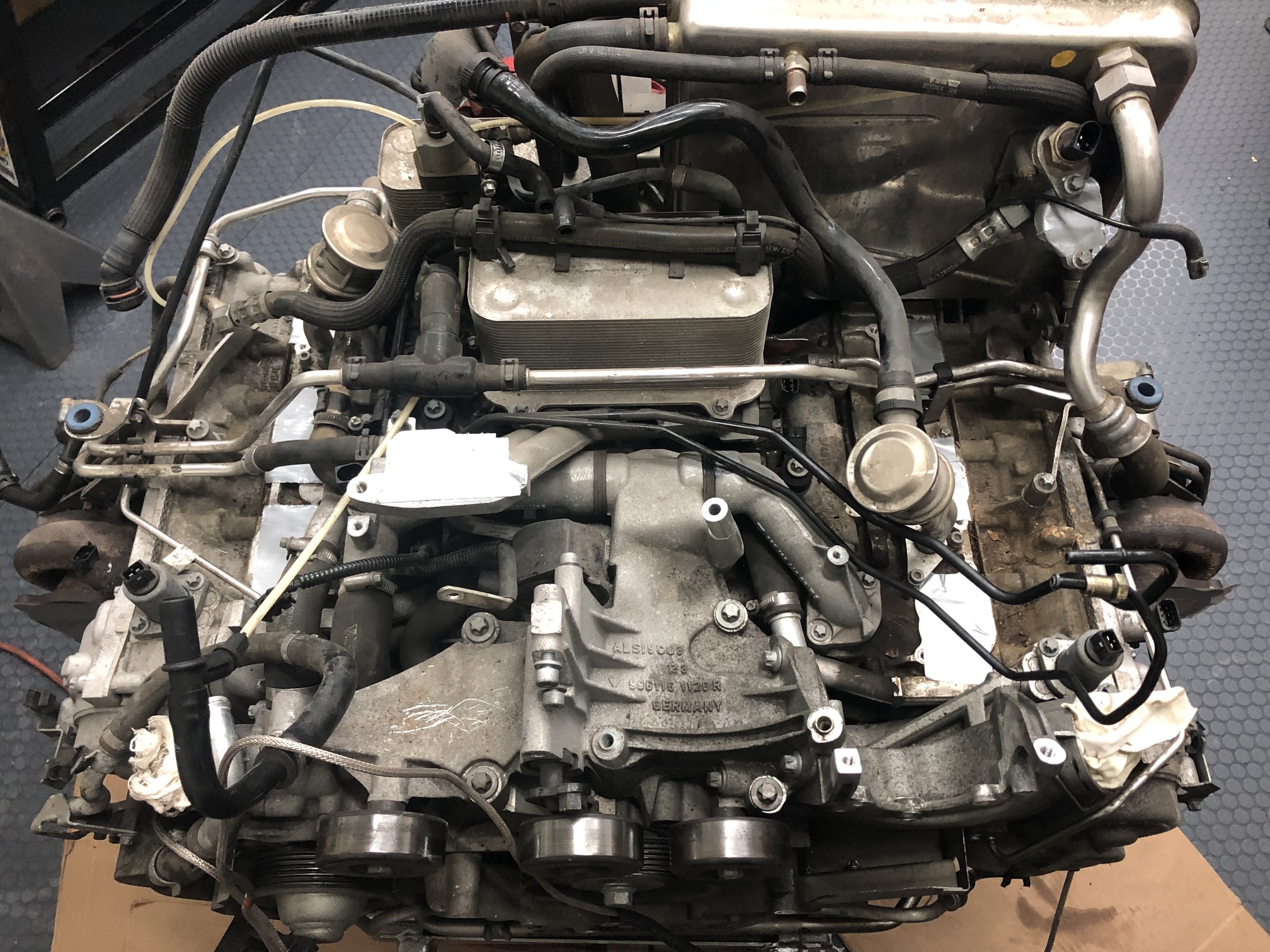
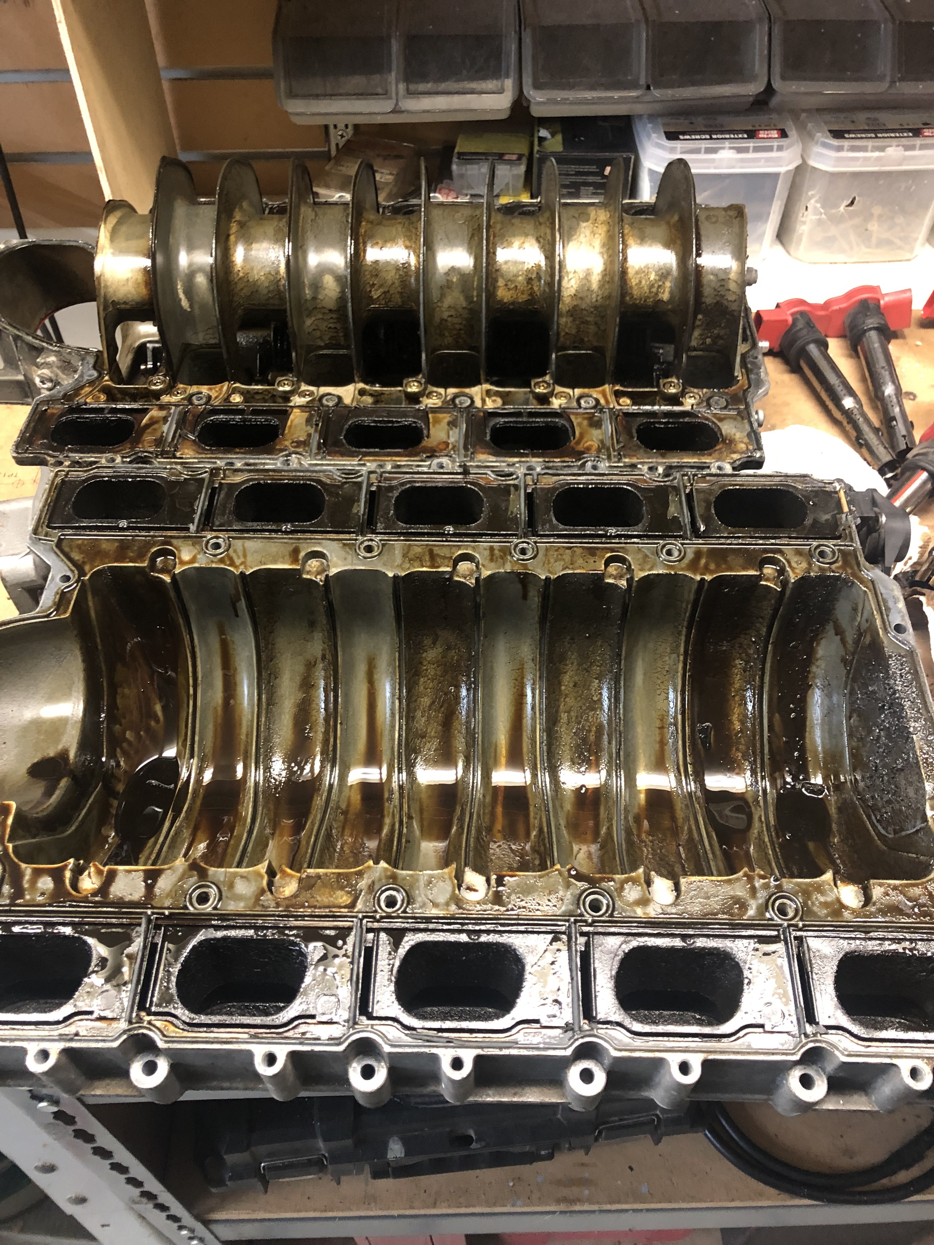
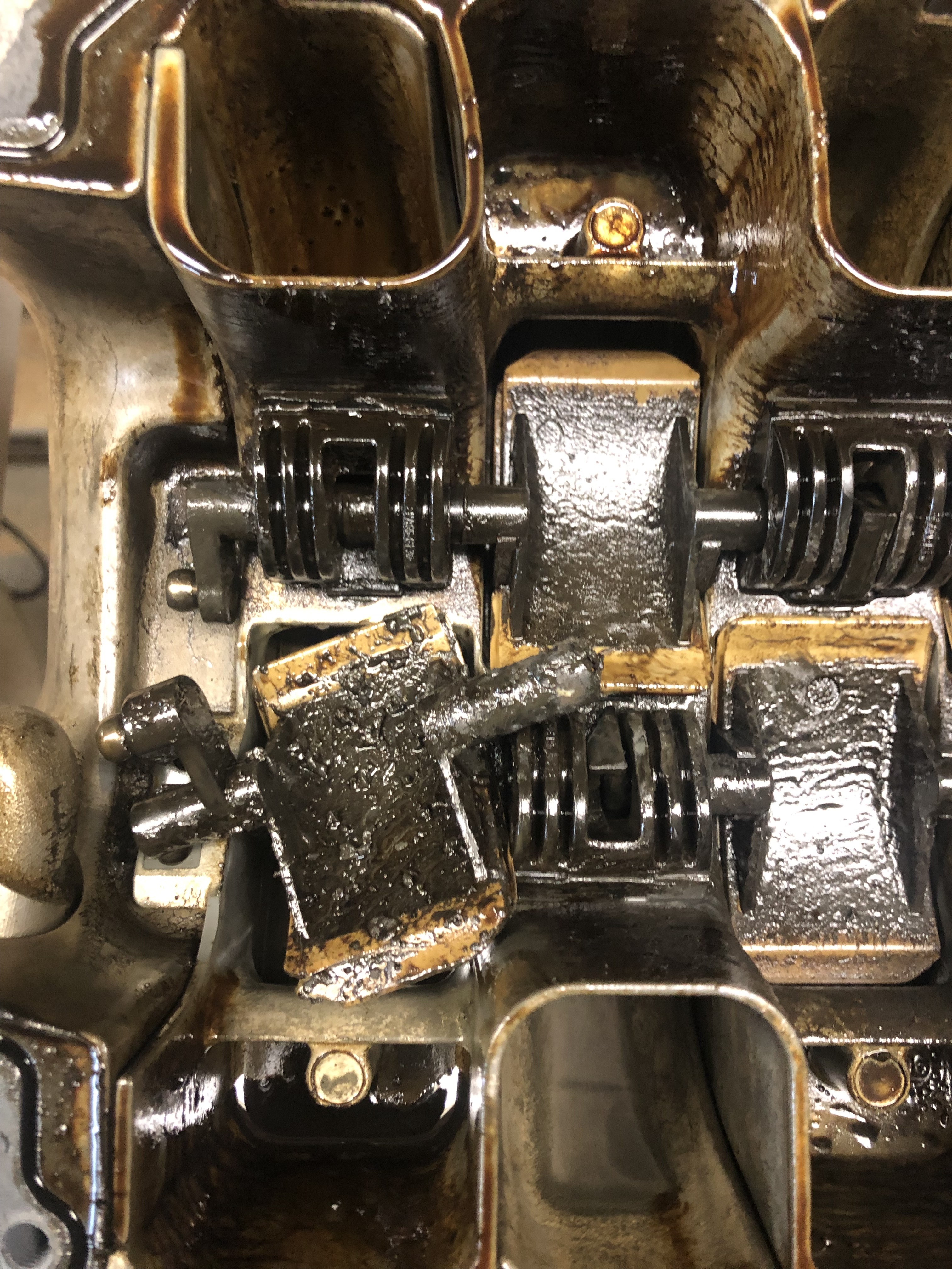
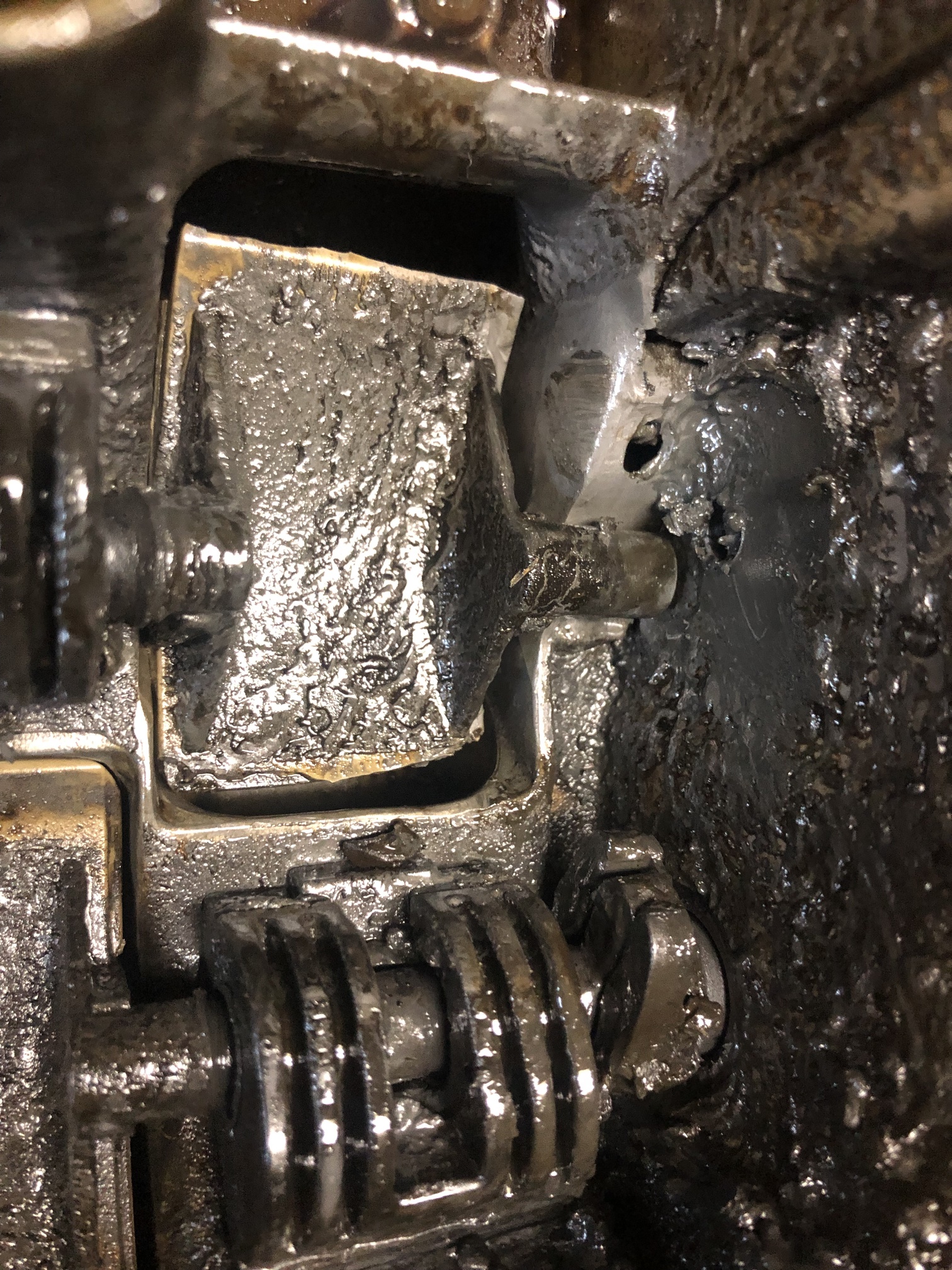
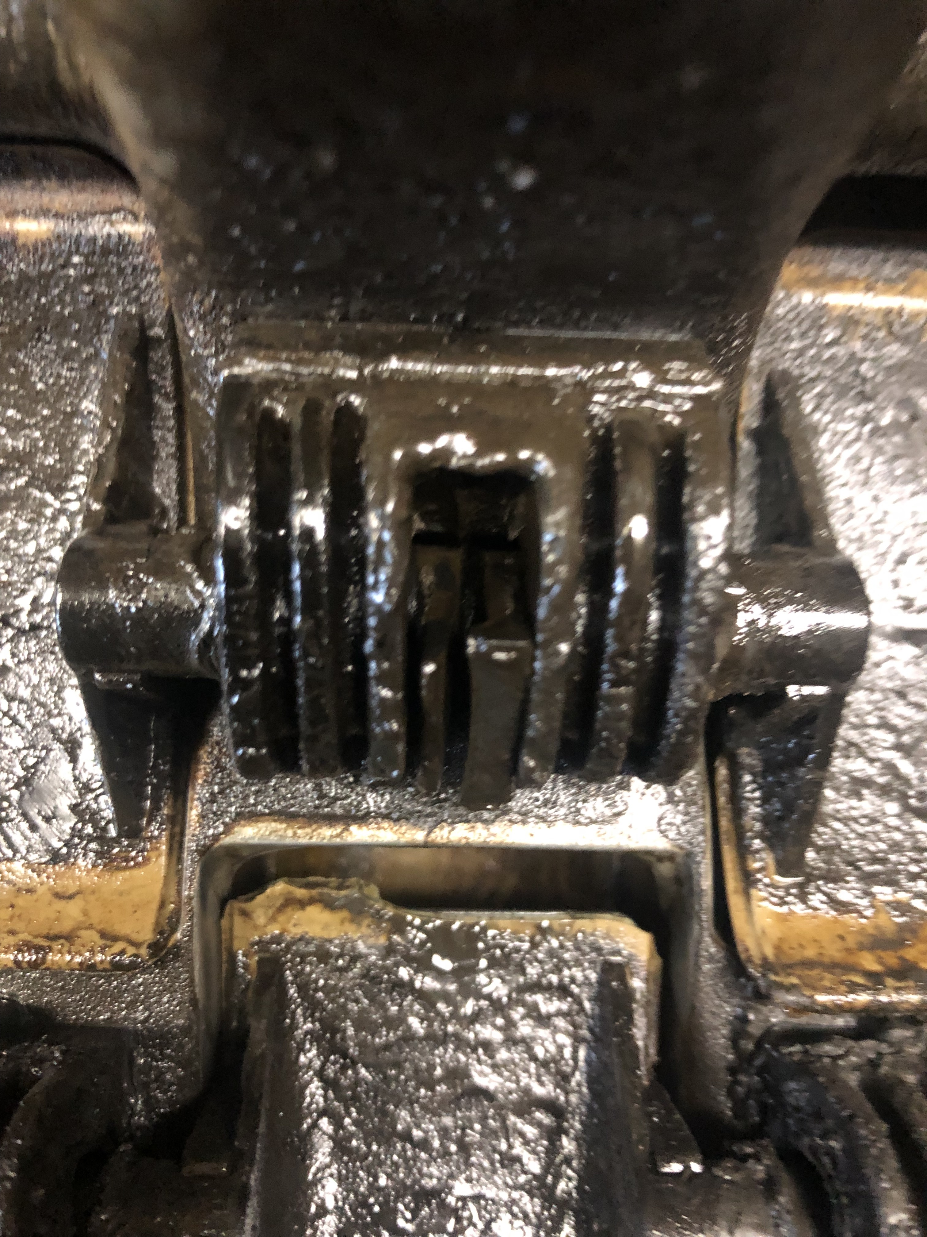
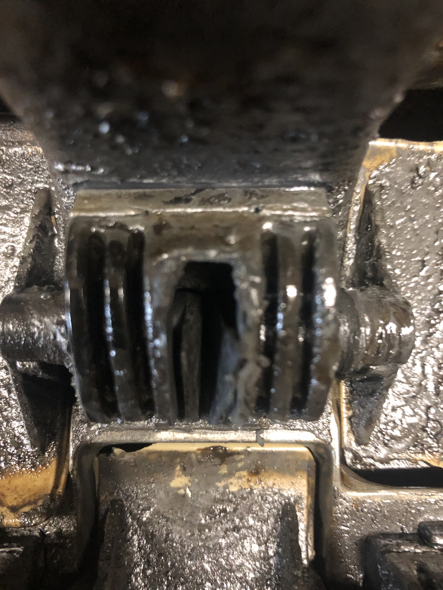
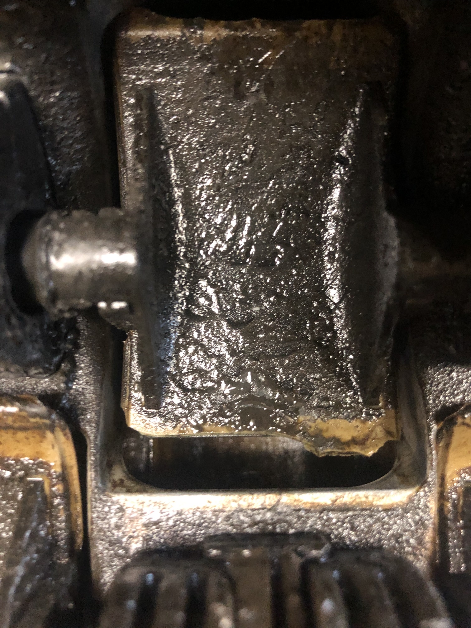
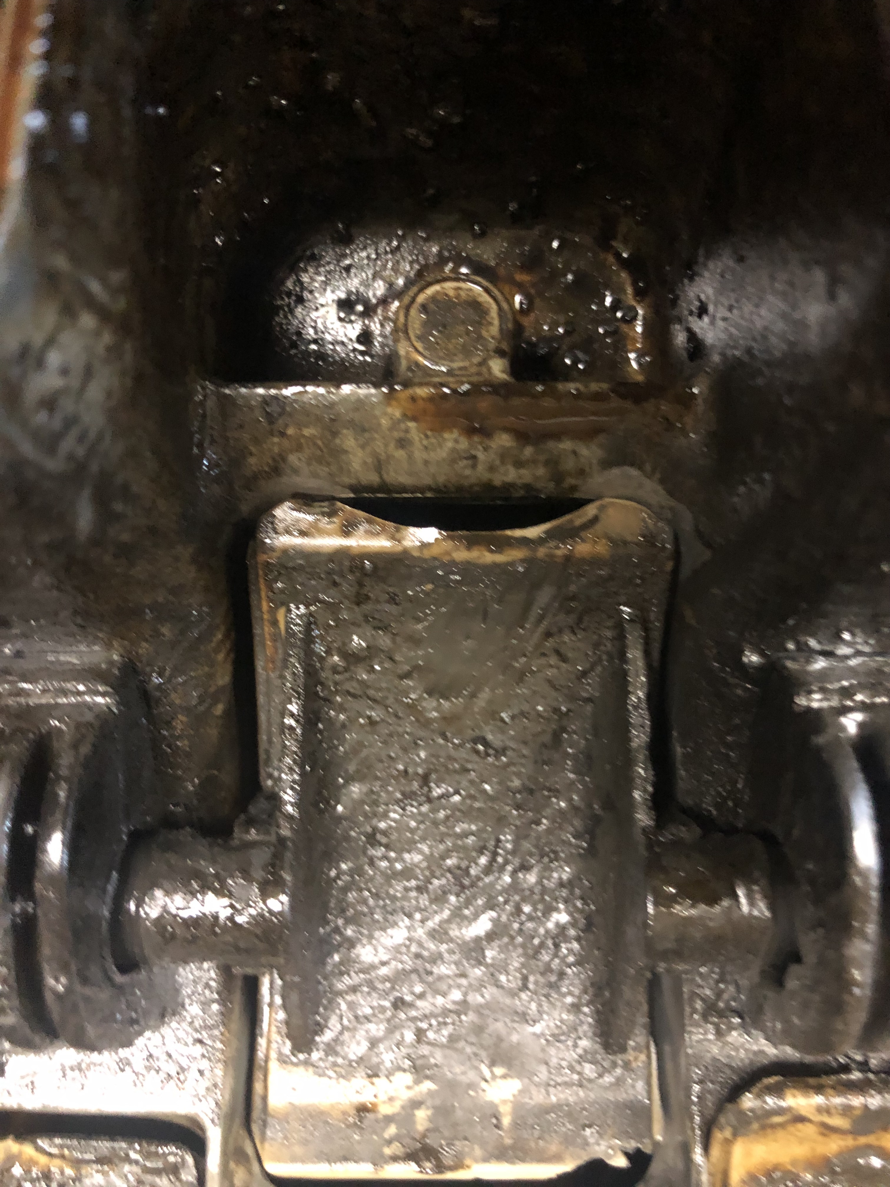
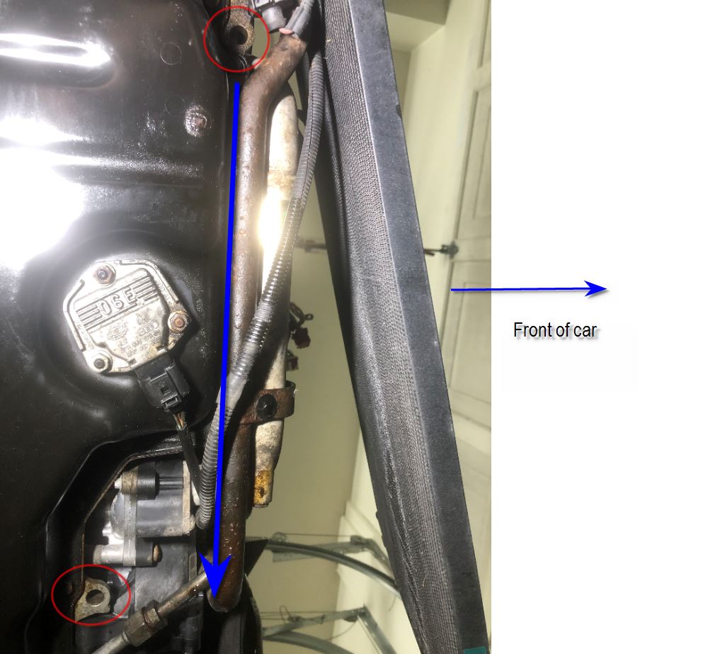
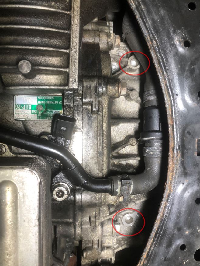
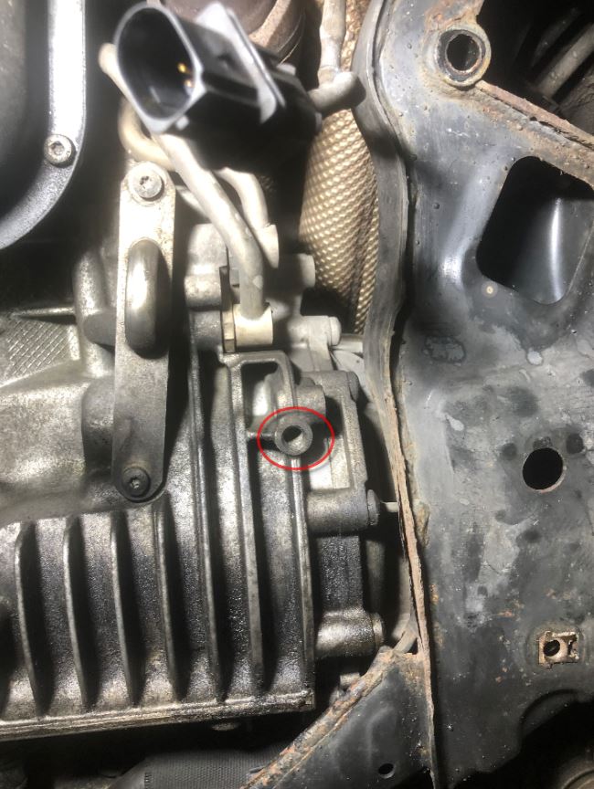
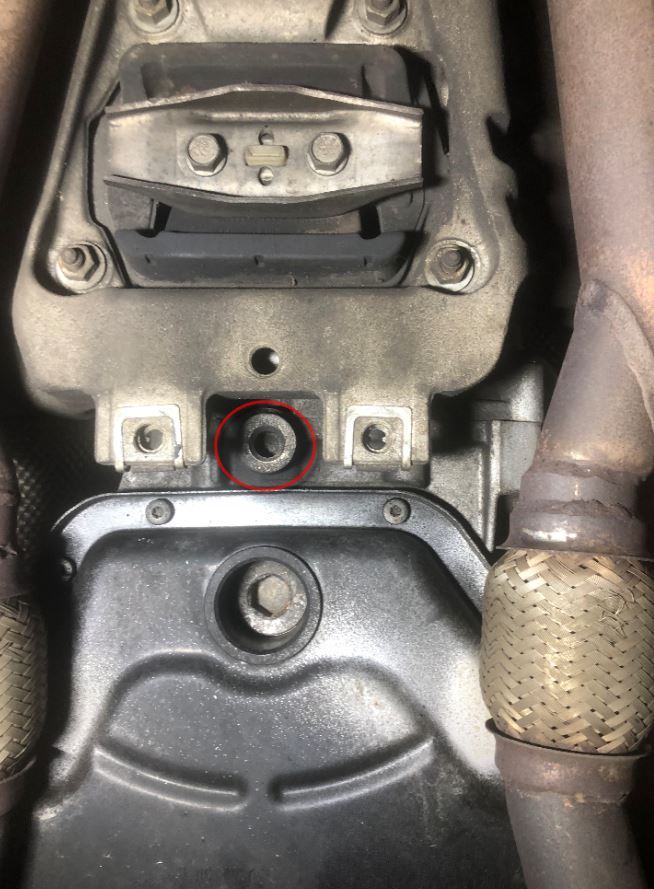
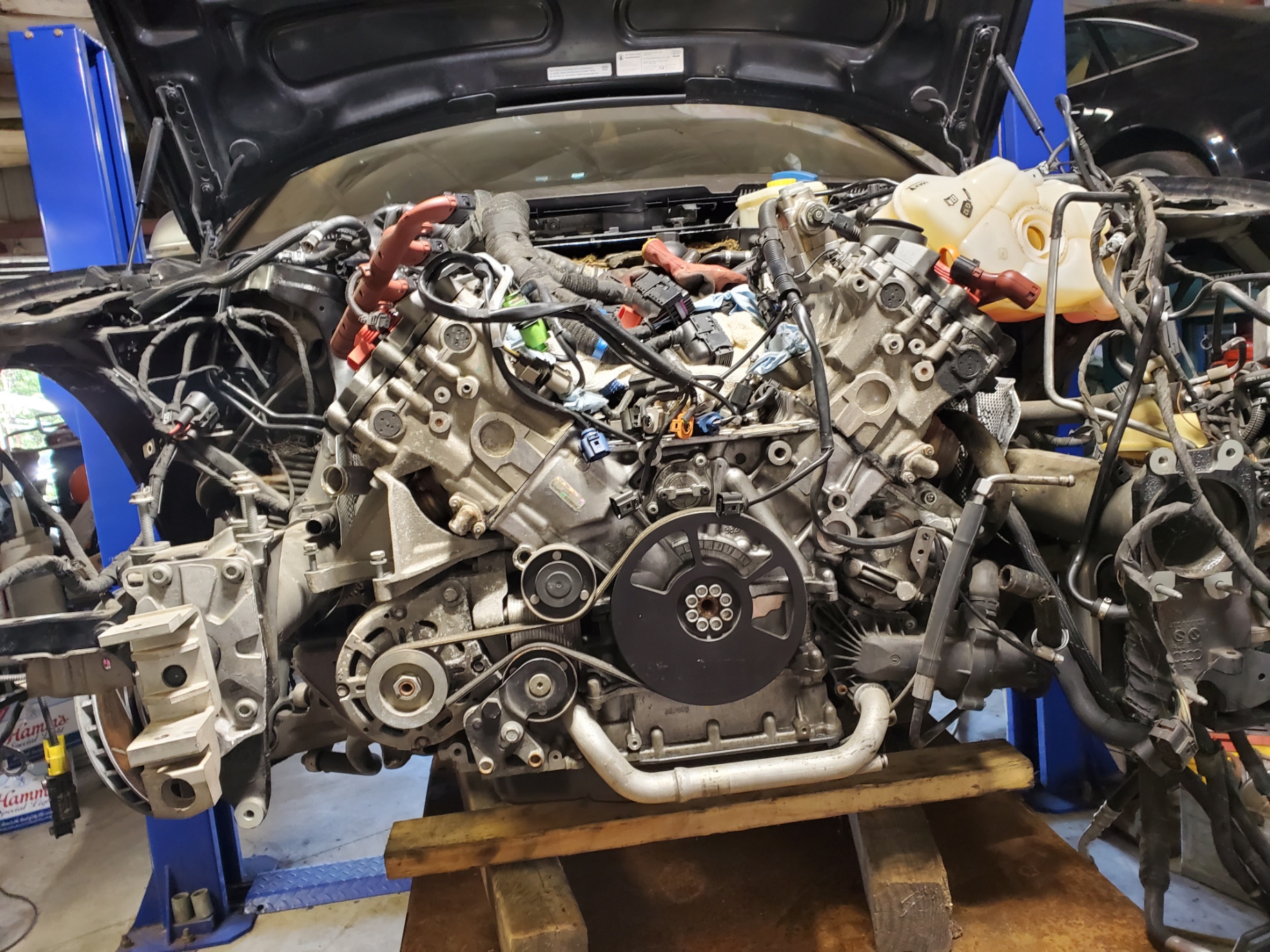
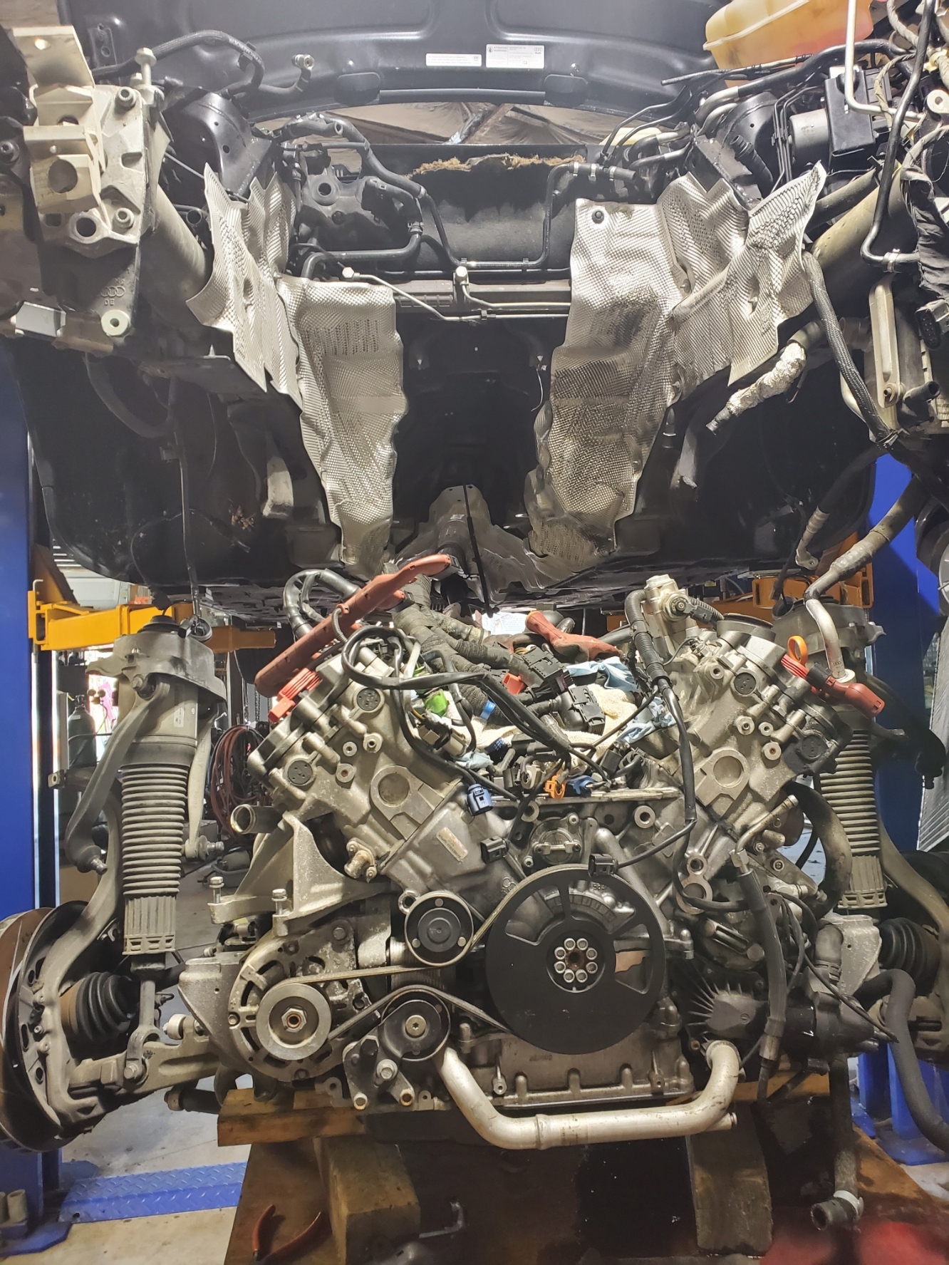
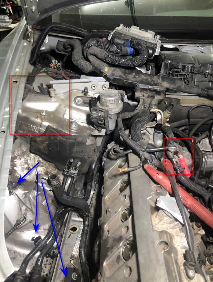
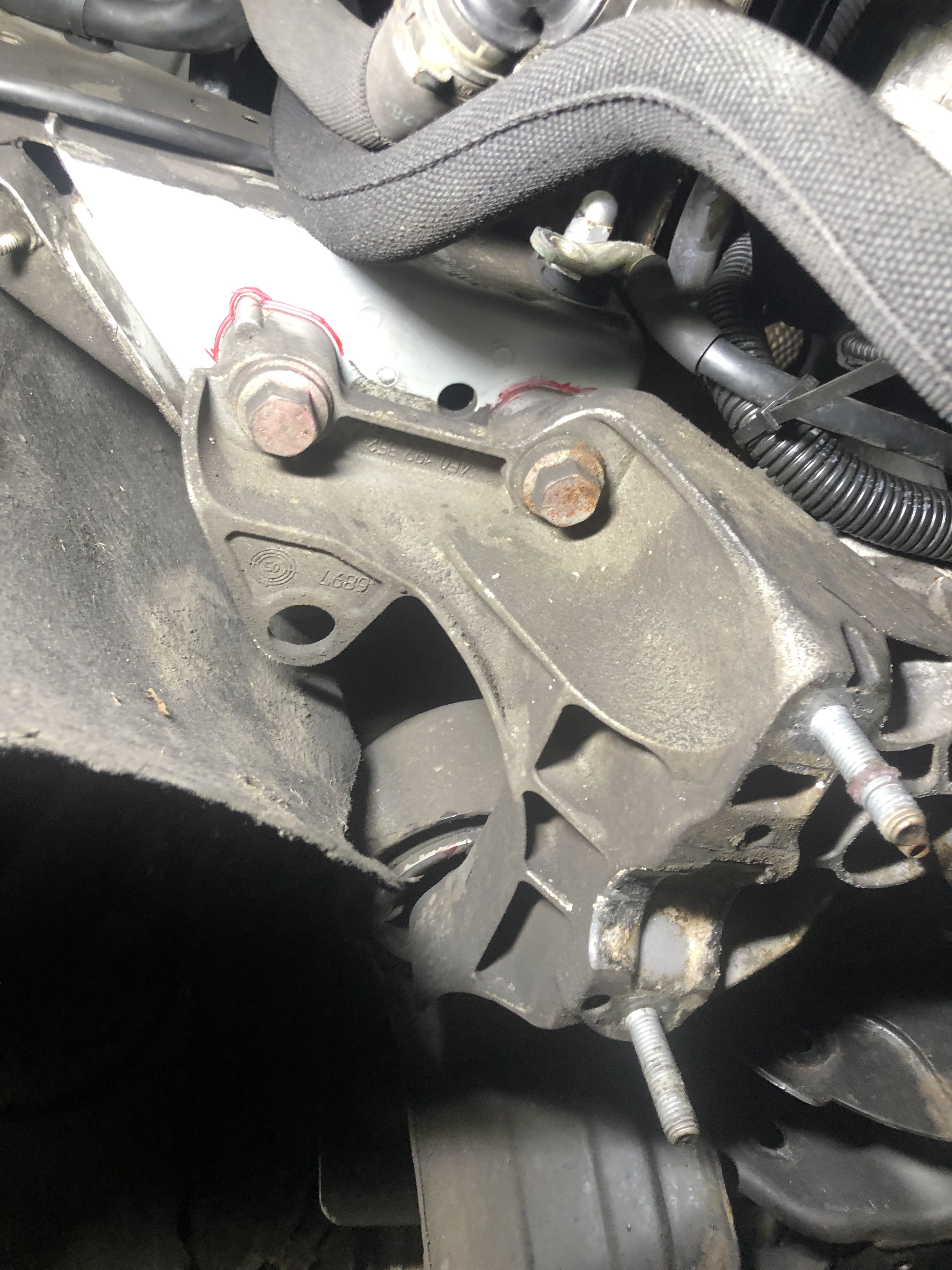
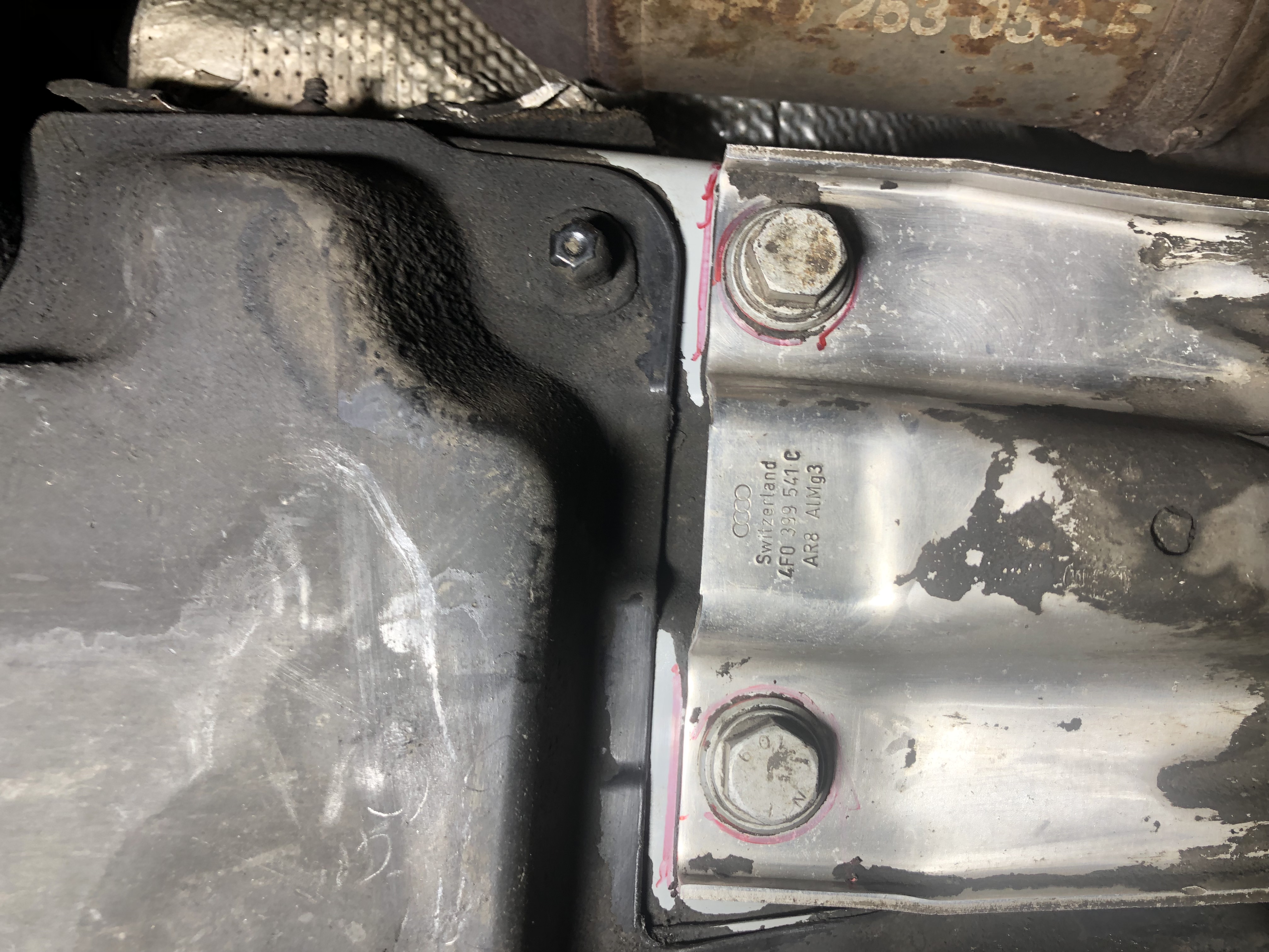
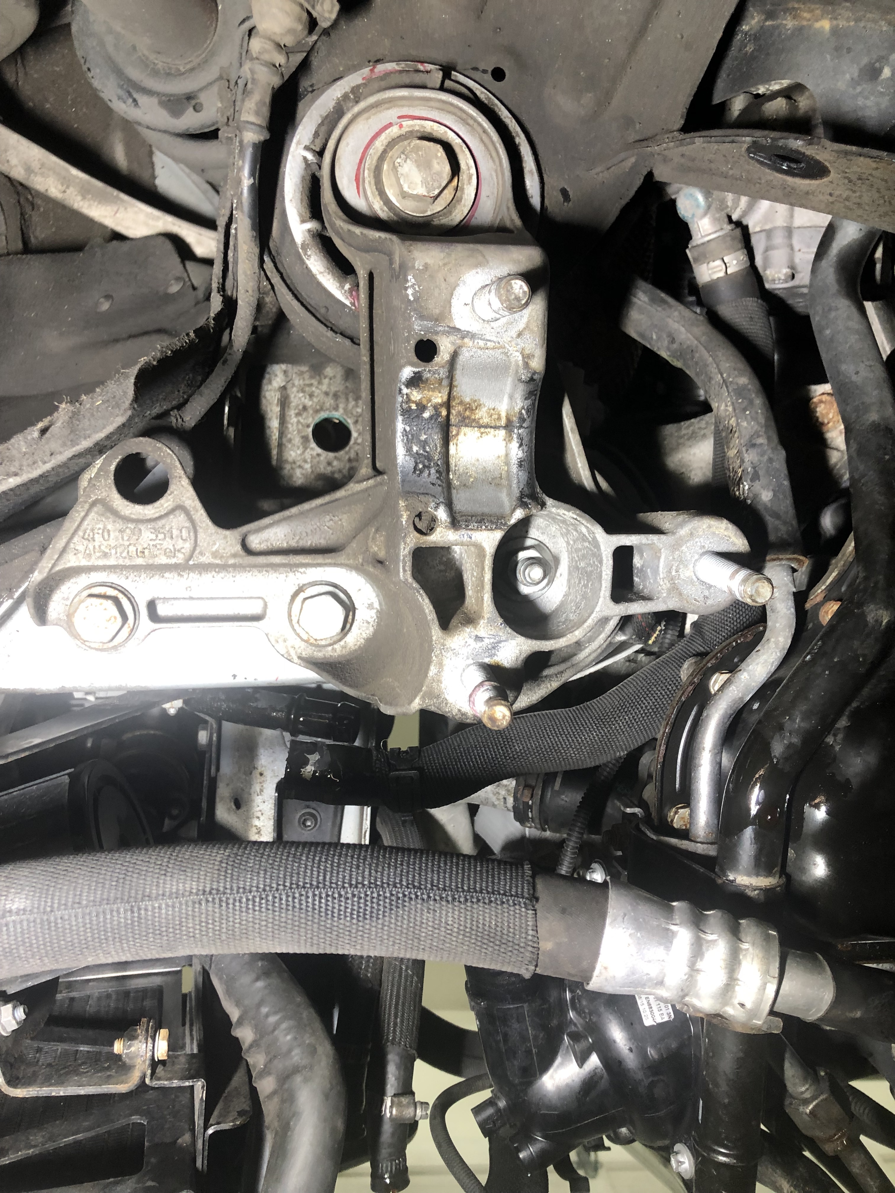
Here are the mounting points (all pictures are taken looking up at the engine from the ground):

Engine Front:

Engine Rear (currently hidden by subframe):

Trans Passenger:

Trans Driver:

Trans Rear:

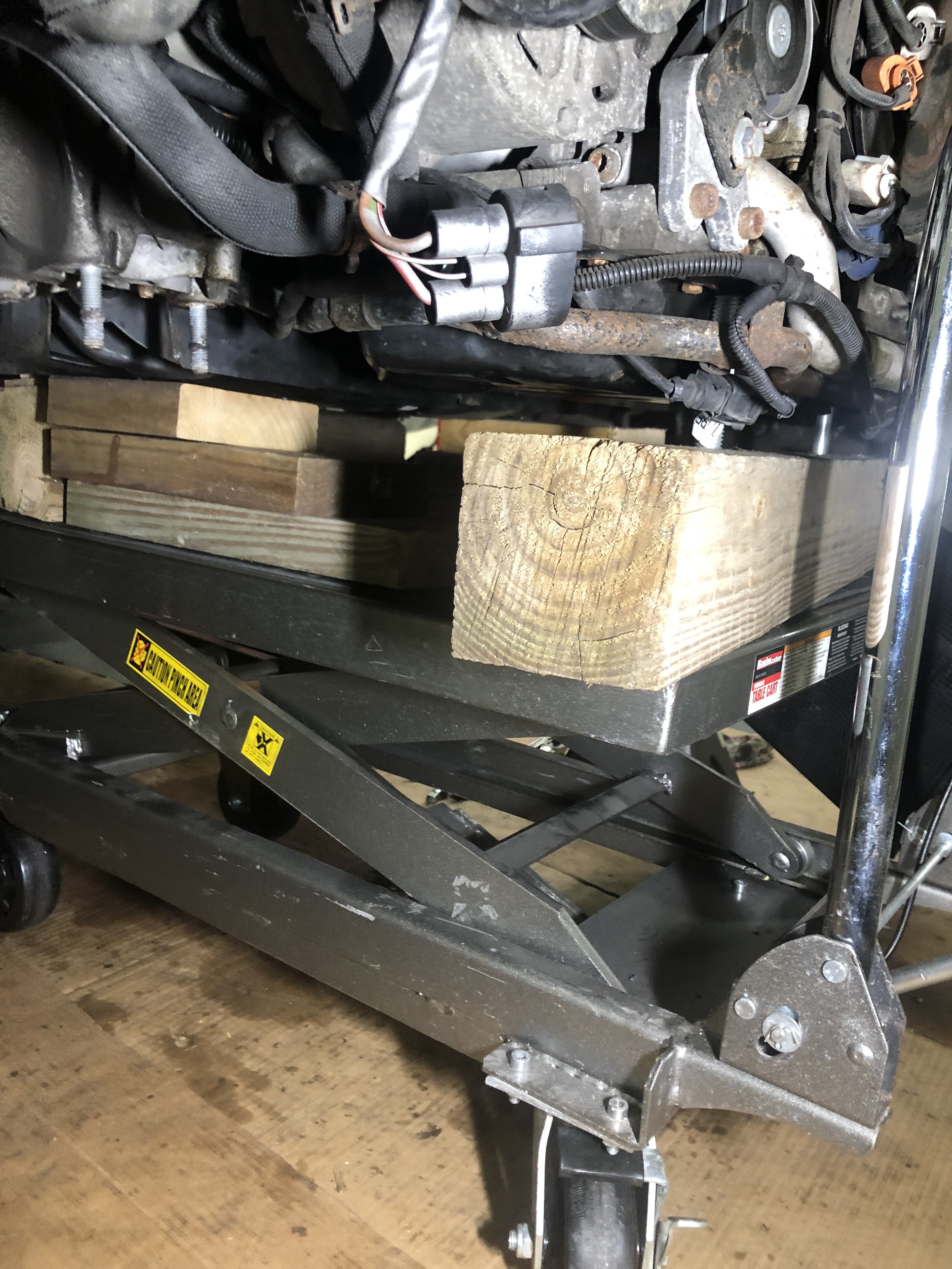
No matter, what I think I am going to make my own VAG tools. I intend to take 4x4 or 6x6 blocks, drill a hole, use threaded rod, washers and nuts (2 nuts/1 washer for top and 2 nuts/ 1 washer for bottom. The hole will be deep enough to thread a bunch of rod into it. I will make sure the rod will fit the holes on the engine/transmission.

Using 2 nuts and 1 washer at the top and another set at the bottom, I think I can thread the bottom bolts enough that a few inches make their way into the block, then I can use the top nuts/washer set to support the engine, spinning them up to make contact. If there are any adjustments to be made for the holes that go directly into the engine or trans, I can make the same spin adjustment from the bottom. I will do another set for the rear engine support holes (that will be hidden by the subframe), just some block for the subframe and then make 2 more block/rods for the transmission. Or I can make a little frame, secure the blocks to the frame and make 3 sets for the transmission. The rear of the frame will hang over the edge of the platform jack supporting the rear most hole.

So a few questions:

  1. Has anyone seen the Bentley and confirm I am not crazy or seeing things?
  2. Are the holes I have ID’d the correct ones?
  3. What do you think about my home made engine support idea?
  4. Can I get away with 2 supports for the trans (I can get an engine hoist on it, or jam some lumber under it once it’s out) or should I build my frame deal?

I think I need to buy the rod/nuts/washers, but I will check around here first.

Again, any BTDT’s would be great. I don’t want to break this thing when I pull it.

Ed

When I was planning my engine drop project, I did a lot of overthinking initially. I scaled the VAG drivetrain table off of a drawing in the Bentley manual that had some dimensions on it. I arrived at 100x100mm squares and mapped out the points they listed for supporting the engine and transmission.

I then overlaid this on a scaled panoramic shot of the bottom of the drivetrain and the motorcycle lift I was going to use to support it.

I thought of making up adjustable pin supports but then I decided to give my head a shake. IMO, this level of effort was not justified for the project at hand. I just added some stacks of 2x4s and shims at three points under the subframe and one under the transmission mount. After I dropped the engine, I used an engine hoist to support it while I removed the subframe. Then I added a few more blocks of wood under the engine and transmission to stabilize it while I removed all the components necessary to separate the engine from the tranny.

I found this picture while going through my collection. The engine/tranny are completely unbolted at this point and weight bearing on the lift. I had to put a jack under the back of the lift as there was so much deflection in the raised position. This is why I added the large castors to support the deck for wheeling it around once it was fully lowered

OK, I won’t overthink it either. Sawing up some blocks now to figure the best positions, then I will use my engine hoist to help remove the sub frame, then put it back down on the blocks.

Thanks for clearing my head!

Ed

Don’t know if this is helpful but here are a few pix of my car from one of the first times I dropped my motor out.

The weight of everything is going to me more than enough to keep things from moving. Make sure you have a good solid surface. If your using a roll table mark the wheels position on the floor with tape and maybe some chalk before you move out do to the work. As you’re going to want to remember the spot you started from.

You’ll want to shim the motor and transmission to obviously be level. You can use the front lip of the oil pan for quite a while as you work out other supporting points after you’ve removed the body

Free advice. Pull the alternator and the wires from the starter and alternator before you get too far in. That will be a life saver.

Pull the alternator & start wires BEFORE pulling the engine?

Ed

The motor won’t come out until you pull the wires from the alternator and starter as they run into the cab and can’t be pulled with the motor. That is a good tip. I would pull them before you start the motor pull.

As Justin said.

You’ll be unable to pull the wires for the starter unit into the engine bay from the body side. They need to go from the engine side and be pulled out in order to drop the motor. You’d only find that out when you start to drop the motor and notice the lines are still there.

LOL, thanks guys. Bentley says nothing about that. The only reference to alternator wires is prying off a securing piece. I am really close to pulling it. I have been a bit side tracked, but I was able to clean up the mounting points and mark up their positions to make sure I get it back where it came from. I am pulling a couple of things for the transmission separation now to make that easier as well.

I will yank the alternator and the starter wiring and I have decided that I will indeed do the motor mounts and starter, but dang all three are expensive. I will go the core/reman route on the starter and save a couple of hundred at least.

Ed

I have only the driveshaft left to remove and it is giving me a hard time. Not even my 25 year old UrS6 was this much of a struggle. I have removed the bolts, sprayed with PB Blaster, let sit for hours, banged it with a wood stick driven by a hammer, banged a screwdriver around the edge where the rusted flange from the trans captures the drive shaft (I have been careful not to beat up the CV joint cover) and I have used some strap wrenches to try and twist them apart, all to no avail. I read about using the engine to coax them apart, but no more running engine rules that out. I hit with PB Blaster again and tapped around the edges to try and get it to work it’s way in and will let it sit overnite. I could try heat, but I don’t want to damage the joint.

Everything else is ready. I noticed the starter wire just wound itself up and around to where the ECU’s were, and since the Bentley already had me removing the bolts that secured it, I cut the zipties and undid the other restraining straps allowing me to pull the wire free:

I have marked the locations of the subframe on the body:

By the motor mount:

Rear Subframe:

And even where the Subrame meets the motor mount piece:

I did use the block/bolt method to support the front of the engine (I couldn’t see any other way to get something past the coolant pipes), and piles of lumber to support the subframe and the transmission and the platform is engaged with the engine/trans waiting for me to get the driveshaft apart:

My hope was the next picture would be of the engine sitting free of the bay, but hopefully that will happen tomorrow. I’ll do some more reading and see if there is any magic out there for this. I will also read up and see if anyone used any heat to separate the shaft.

So close, yet so far.

On a funny note, I must have not cleared the original number “1” on two items I ordered, so I wound up with 110 exhaust studs and 112 timing chain tensioner screws. I will return them along with the unneeded throttle plenum gasket.

Ed

Well that didn’t take too long. Found a post suggesting to thread a bolt partially back in and use an air hammer while pulling back on the shaft, and voila, shaft is free.

I am too tired to go after the subframe bolts tonight, so I will get this beast out tomorrow. Then the fun begins.

Ed

Ed thats exactly how it looks when I do it. The wood shim method works very well. Same cart I use. Other than checking a few lines here and there. Should be a smooth drop.

Great job.