
You have to use a new nut … not reusable and in such cases I would personally never reuse the bolt either 
Yes, I have a new nut, as well, as the ball joint separator was not nice to it. It took about everything I was willing to give that separator bolt to get this thing to move…actually I had to keep the separator installed, and use an impact gun turned down on the bolt head, while adding heat to the knuckle to get it to turn. Once it was turning I added WD-40 while I was hitting it with the impact gun…and removed the separator to use a wedge to drive it side-to-side. After the bolt was out I used a long wire brush to clean up the ID, so it is now ready for a fully-coated bolt with anti-seize to go back in, and a new nut!
Going to try the same process tonight on the other side…wish me luck, and hopefully it takes less time after the learnings on the first one!

Well…used the same process on the other side, soaking the knuckle in WD-40 and PB Blaster for a few days, heating the knuckle to the point of deforming the boots on the links, and then trying to turn the bolt out. This time, the head turned right off…ugh. So, I used the method of pulling the bolt out by the nut: first starting with 1 washer, then 2, then 3, then a larger nut, then a nut and a washer…you get the ideal. I had to keep the knuckle really hot and then the nut would pull it. The end of the bolt threads finally hit the other portion of the knuckle, and I couldn’t get the nut threaded off any more, so I have to use a hammer to bend the bolt to the side, and thankfully a solid punch through the hole (from the broken off head side) was able to push the remainder of the bolt out of the knuckle. A new bolt and nut and it is back in with the new links…front end is a lot tighter now! I do notice some high pitch sounds from the front left wheel when I am rolling slowly, and a soft rumble, so I am afraid I have a wheel bearing going out. Back into the shop in a few days to fix the bearing, and continue to chase these misfires, and one remaining oil leak (I think it is the main seal leaking again because when we put it in the seal started at an angle and we weren’t able to straiten it, so we used a block and just put it in…seemed to hold for about a week, now leaking again).
I also did the crank seal and thought it was leaking again but it turned out to be leaking a little higher up.
Have a look at my thread here…
https://forums.audirevolution.net/t/oil-leak-new-in-front-of-v10-5-2/18937
I purchased the balancer shaft O-rings (small front one, and larger rear one), and the oil cooler orings, so plan to do all those when I go back in this time.
Now that I have the front suspension links in I warmed up the engine and drove it for a while at 2-3k rpms. It runs pretty well at temp, out on the road, but just a very subtle shake at idle at stop signs. Brought it back home and parked it in the garage and the heat soak test showed the rail pressures rising like they are supposed to, so at least the fuel situation seems to be much better than before…unfortunately, the new HPFPs haven’t completely fixed the misfires, still get an engine light to come on during almost every drive right after it starts.
I did coil/plug swapping earlier in my misfire diagnosis process, to verify that the misfires didn’t follow the parts, but I am starting to wonder if maybe all of the plugs are causing slight misses, and possibly those cylinders are more prone to recording the misfires, is this possible? Does anyone know what the ECM uses to trigger the misfire codes, is it knock sensors or current readings on the plugs/coils? The plugs that are in the car are SKP brand, and don’t have the triple ground electrodes, it only has 1 over the top. Is it possible these plugs aren’t hot enough since they aren’t R rated? I am ordering the NGK 5547 ones just to make sure these aren’t causing problems. May consider coils as well…just want to make sure I have every possible known issue covered before having to take the car to Audi for help in diagnosing these pesky misfire codes!
Thanks, I am back in there, and it does look like the main seal is holding strong! There may have been a little wetness from above the main seal, so I have the balancer shaft Orings changed, and have the oil cooler out to change those, two, as well. The main leakage, though, is coming from the front left (drivers) side. It is really wet below the water pump. Does anyone know if there is a seal on the shaft that drives the water pump, and does this one leak, too?
There is an Oring, that sits between pump and engine block. The shaft itself is sealed inside the pump, and this seal is not replacable.
I have the water pump out, and when I turned it over, oil ran out of the breather hole. I am pretty sure this means the oil I am seeing under the car on this side is being pushed past the drive shaft and into the water pump housing, and then out of the breather hole on top of the housing and dripping down the side and to the bottom attachment bolt…then onto the ground. I did not see any oil in the coolant so I expect there is a seal on the water side of the driveshaft that is still holding strong. I have ordered a replacement water pump and plan to replace the Orings in the block for the driveshaft and the outlet port. It looks like the pump I ordered has both of these included, along with the seal for the interface with the plastic water housing.
1 Like
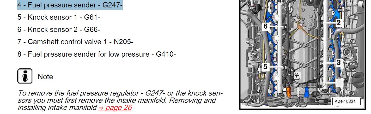
Back to misfires…I am installing the new NGK spark plugs and noticed in two of them, #8&9 cylinders, that a small bit of oil was present at the base of the plugs. Since I am very confident that the valve cover gasket is not leaking, it would appear the seal between the head and the intermediate plate is leaking…ugh, not another s6 blessing  . I am not eager to pull the engine for such a small leak so I am brainstorming methods to “slow down” the leak at this seam. One idea I had was to use a silicone-based adhesive tape, or some kind of flashing-tape with an aluminum backer, to cover the seam…such that it is stable at high temperatures and will provide some kind of barrier to oil pushing into the plug hole. Does anyone know if this oil is under pressure adjacent to the plug holes…are the cam journals right there? Another idea I had was to rough up the surfaces of the head and plate at the seam and use JBweld to bridge them to cause a higher resistance path for the oil, but I am afraid different thermal expansion coefficients will cause a fairly rigid body (after the JBWeld sets up) to break free of the metal surfaces, eventually…thus right back to a leak, and now with plastic pieces all over in the plug cavity. I understand everything I attempt will be a “bandaid” but I don’t want to pull the engine to fix a really small leak…its just in a really bad place! Any other methods or ideas people have, short of pulling the engine out? Is it possible to lower the engine enough to get the intermediate plate off and fixed without actually pulling the engine? Also, as a side note, I am purchasing the coils in addition to the plugs…the ones that were in there are no-name so likely from China…so maybe can’t take the heat that this engine puts out? If figured for the exact $200 on top of the $100 plugs I might as well be hitting this misfire issue with as big of a hammer as I can throw at it, since I already have it apart!
Ted, I think there is a thread on here that talks about using a portion of a bicycle tire tube on the coil pack to create a seal between the coil pack and the head. From the thread discussion, that seems to be a good, functional solution. I haven’t done it yet, but I did carefully apply sealant (permatex ultra black) at the joint inside one of the spark plug tubes and it hasn’t leaked again so I bet the bike tube does work. I spent a lot of time making sure the sleeve was very clean. I, personally, would not use JB weld - I don’t think it’s necessary.

Last night I used sandpaper on a drum to lightly scratch the two plug walls that are having leaks, and then wiped them down with rubbing alcohol. Then, I used a dowl on a drill to apply silicone Red sealant to the walls. The dowl is the same size as the coils so I am confident the coils will fit down the hole afterwards. I used a rag patch in the bottom of the plug hole so nothing fell down into the cylinder…and I will be using a grab tool to pull the small rag patch out of the hole after the silicone dries. I wanted the walls to be continuous so they are less likely to peel off. You can see in the picture the walls are pretty well coated, so I hope it holds the oil back!!
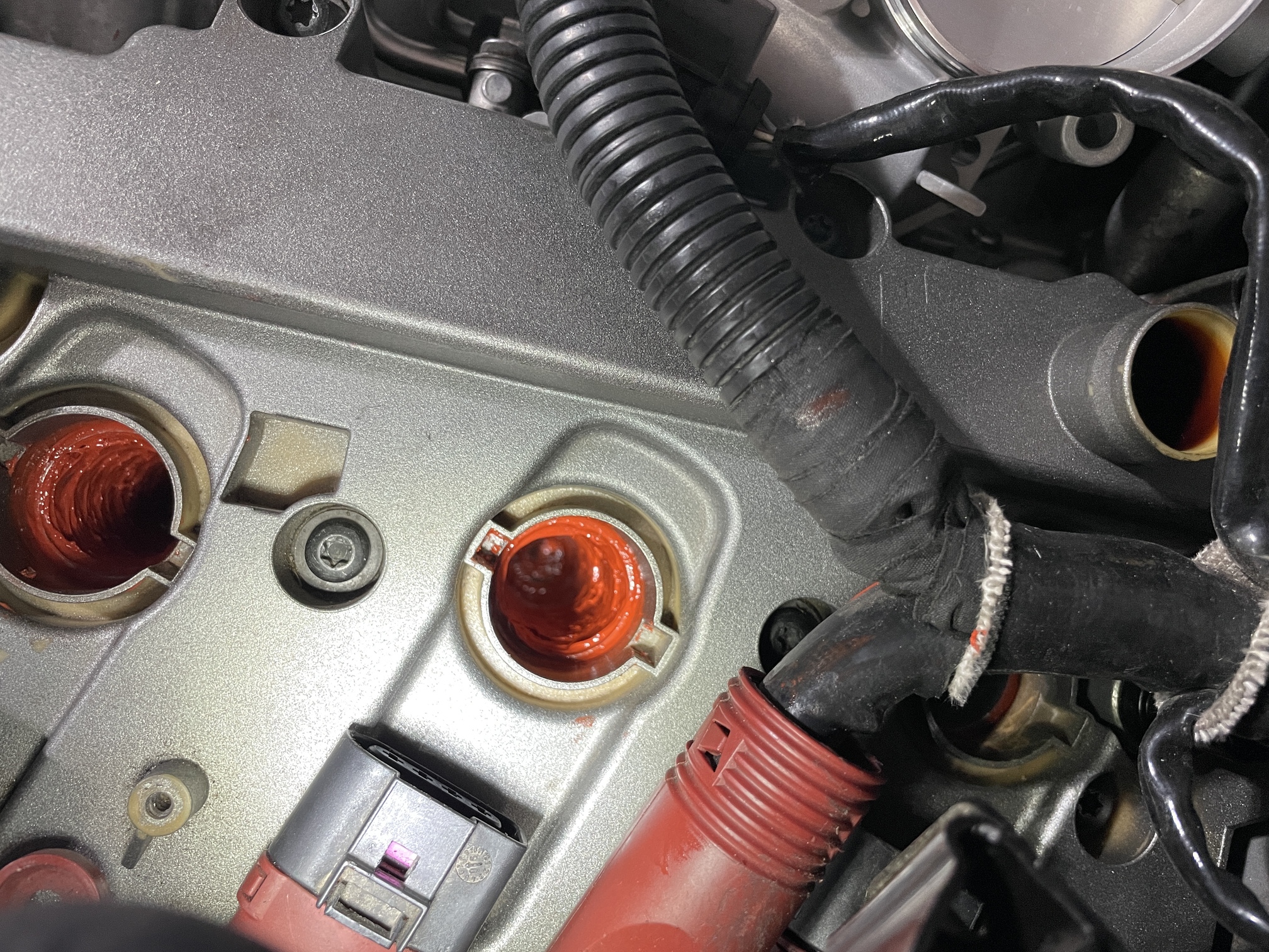
The plugs with the black rubber boots will fit the plug hole but not apply any load to the ID - where the oil is leaking from. The idea of the rubber tire wrapped around the coil is to insert it into the plug hole such that the number of wraps of the tire will cause interference with the walls, and therefore the rubber tire will compress during assembly, and push on the walls/seam where it is leaking. It looks to me that there are actually two seams in the plug hole below the valve cover gasket that could potentially be leaking. With my method of applying a layer of silicone sealant I am trying to create a surface seal that is rigid enough that low pressure oil can’t push through it…but still expands and contracts with the metal without breaking off. Any pressure behind the oil and nothing will hold it back, but since it is just a very slow trickle, I hope that the pressure from the sealant will hold it back once it sees the resistance. This is a much faster fix than pulling the engine to replace the gaskets between the head and the intermediate plate!
Today I found a post on how to test the coils for resistances and opens (here is the link
and instructions below. I had a 100% correlation between the markings on coils and the connection between housing grounds and pin4 being an open circuit instead of connected with very low resistance…like 0.1ohm. I did do swapping of two coils and plugs between cylinders so I am wondering if I am missing some grounds on these cylinders, as well. I am going to go to the car connectors and very pin4 is connected to the body ground at the battery post….and if not, fix those terminals or ground wires. The misfires I am seeing appear to be related either directly, or partially, to the coil pack housing not being grounded to pin4 properly (or at all). I am wondering if during the removal process the top gets rotated (to loosen them slightly) and the connection from the metal collar of the coil to the ground is broken. Maybe the coil isn’t impacted as much at higher rpm’s since the frequency of the signal wave is greater and therefore more energy is present in the coil and so it doesn’t need the shielding? I may talk to my electrical engineer friend and see what he thinks about this theory! I have all new coils being installed, and will be checking connector grounds, so we will see how the misfires react.
To ohm out your ignition coils:
-
remove ignition coil
-
Set meter to measure resistance(ohms)
-
Place either lead on pin one and hold it there (you’ll see the pins labeled when you look into the coils receptacle). I have alligator clips on my leads which does make it easier to do but it can be done without them obviously.
From pin 1 to pin 2 you should read around 70k-80kohms much higher or lower indicates bad/failing coil.
From pin 1 to pin 3 you should read around 70k-80k ohms much higher or lower indicates bad/failing coil.
From pin 1 to pin 4 you should read OL (open circuit)
From pin 2 to pin 3 you should read a range from 350-500ohms much higher or lower indicates bad/failing coil.
From pin 2 to pin 4 you should read OL (open circuit)
From pin 3 to pin 4 you should read OL (open circuit)
Place a lead on pin 4 and place other lead on the metal surface of the coil and you should read very low resistance only about 10-15ohms. Pin 4 is your grounded (neutral) pin.
If meter is displaying any measurements between pin 4 and anyother pin then coil is bad or failing as that would indicate a short to ground.
1 Like
I tore into one of the coils and it looks like there is a small tab that is bent up on the sheet metal shield that is supposed to contact a metal finger on the coil top to ground it. It looks really easy (and I think this is what happened to 5 of mine) is the metal shield rotates, maybe bending the tab on the thin sheet metal shield) and loses contact or has little contact with the metal finger. Once this happens it looks like it can produce high resistance between pin4 of the top and the shield , or no longer grounds it at all by showing an open. I still don’t know if a grounded shield makes the difference in a coil working or not but since the coil is supposed to see a square wave of differing frequency it is possible the spark plug itself is creating noise that gets back on the signal wire if the plug is improperly grounded. I will be starting my engine soon to see if the new coils fix my misfires!
1 Like
New coils fix a lot of issues. I’d love to hear how your attempt to keep oil out of the cylinders works as well. keep us posted on that.