RS5 carbon clean DIY

Upper Intake Manifold Removal

The first round will essentially be unplugging a whole lotta stuff. A little tech tip if you do not trust yourself, take painter’s tape and each connection that you separate, whether it be electrical, coolant hoses or otherwise, mark each side with the tape and write a corresponding letter on the ends that connect together. I will say this…most of the lines and connectors are routed as such that it’d be hard (but not impossible) to mix them up so use common sense. And take photos with your smartphone for reference!

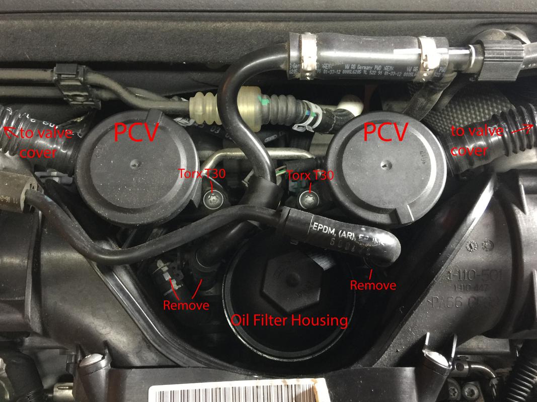
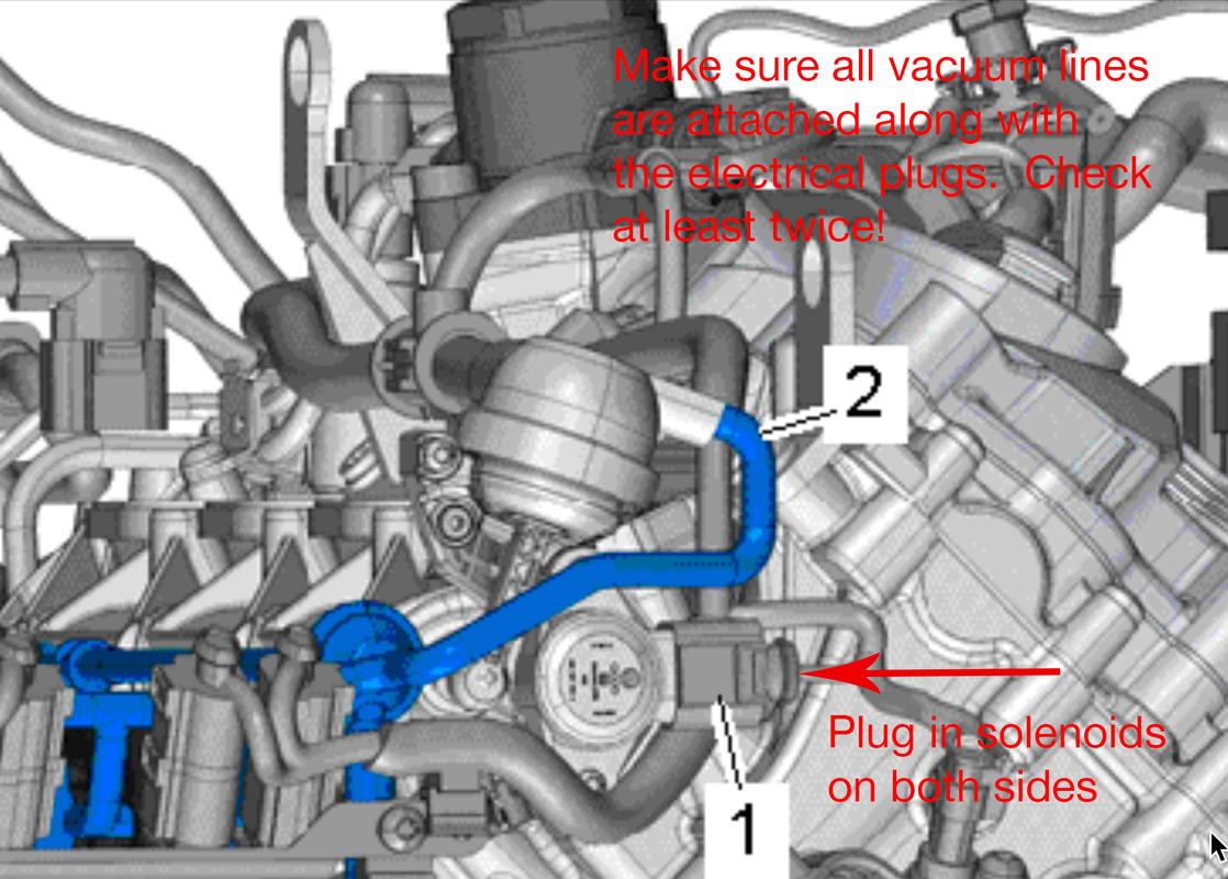
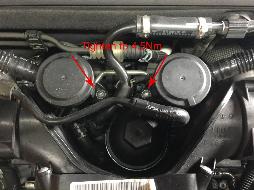
We’re going to start at the back with the PCV valves. They’re the two big round things in between the throttle bodies. A single torx screw holds each one on. The end of the tube connects to the breather ports on the valve covers. Pinch that end off first, then remove the two bolts. While you’re back there, you’ll need to remove each and every hose that’s attached to the manifold. Pliers work fine.

What it looks like in real life. Note, the FSM left off a few hoses so again, use common sense and look at everything. It’ll be obvious what needs to be removed.

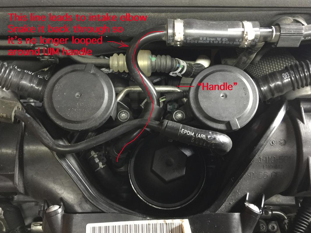
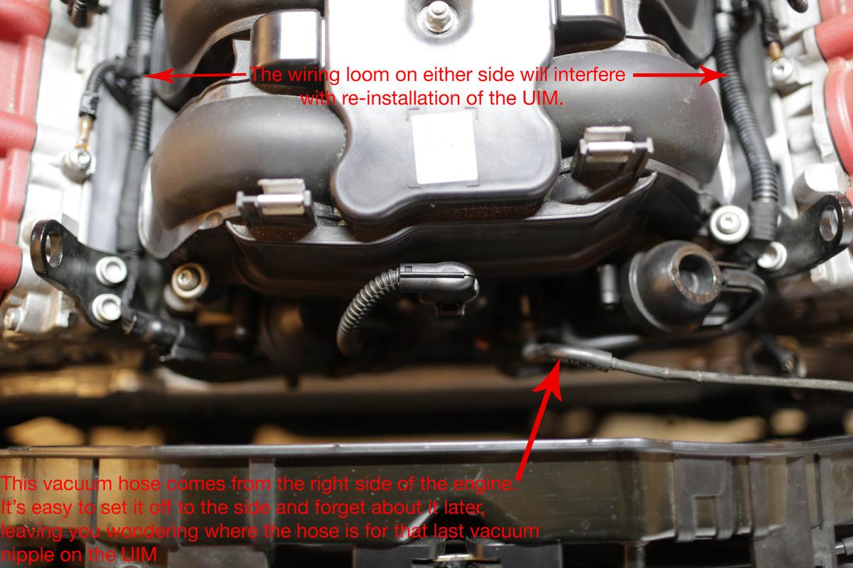
There is one vacuum line which connects from the passenger’s side intake elbow to the PCV system elsewhere. The UIM has a metal grab handle (or support depending on how you look at it) and this vacuum line literally loops around it and prevents you from lifting the UIM up and off the engine. You’ll need to snake that vacuum line through a bundle of hoses and wires and away from the back of the intake manifold. I’ve outlined the hose in red. By the time you go to remove this line, the PCV valves and other hoses should be off making it much easier.

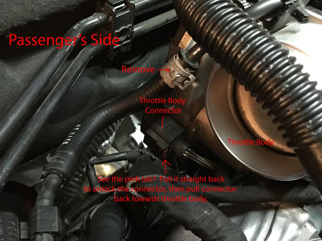
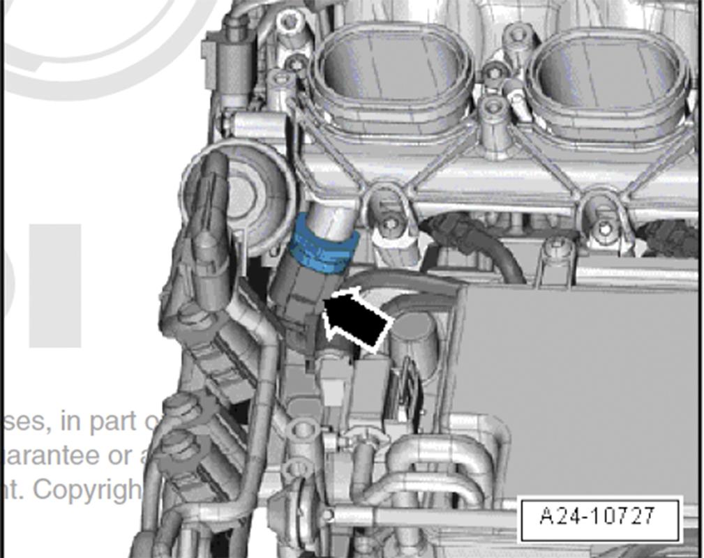
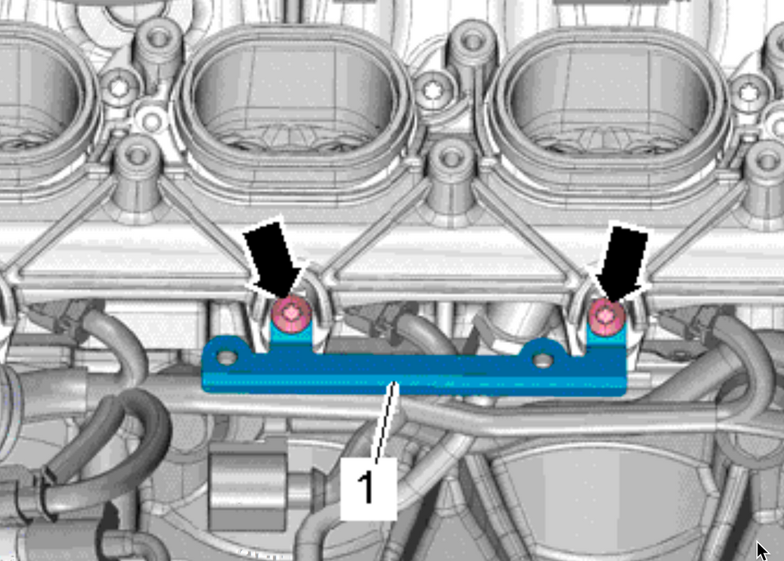
We’re going to unplug the throttle bodies next. Obviously there are two throttle bodies and there are naturally two plug connectors. Each connector has a little pink tab which you pull straight back with the aid of a screwdriver. Once you’ve unlocked the connector, it’s easy to get off.

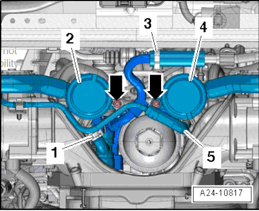
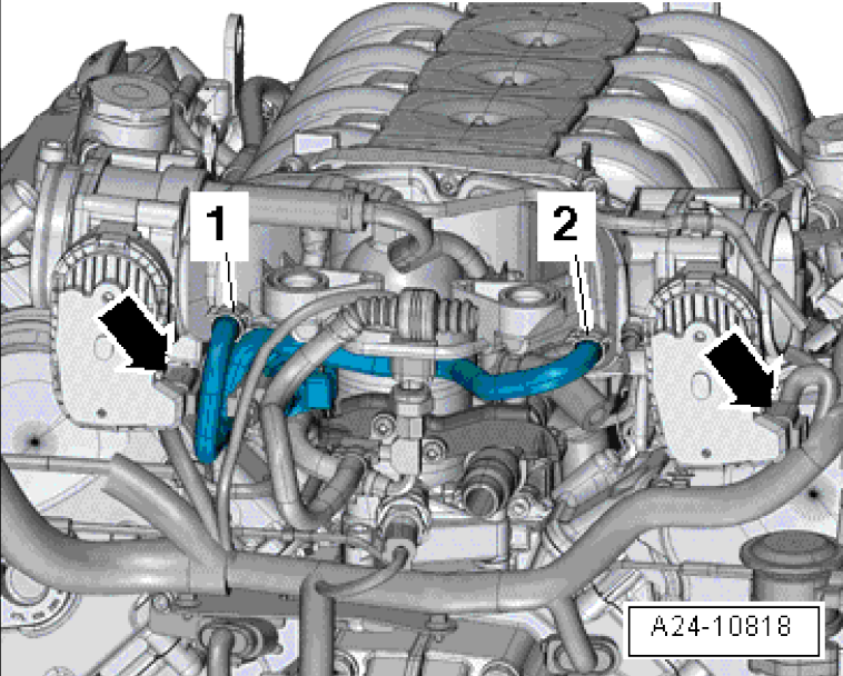
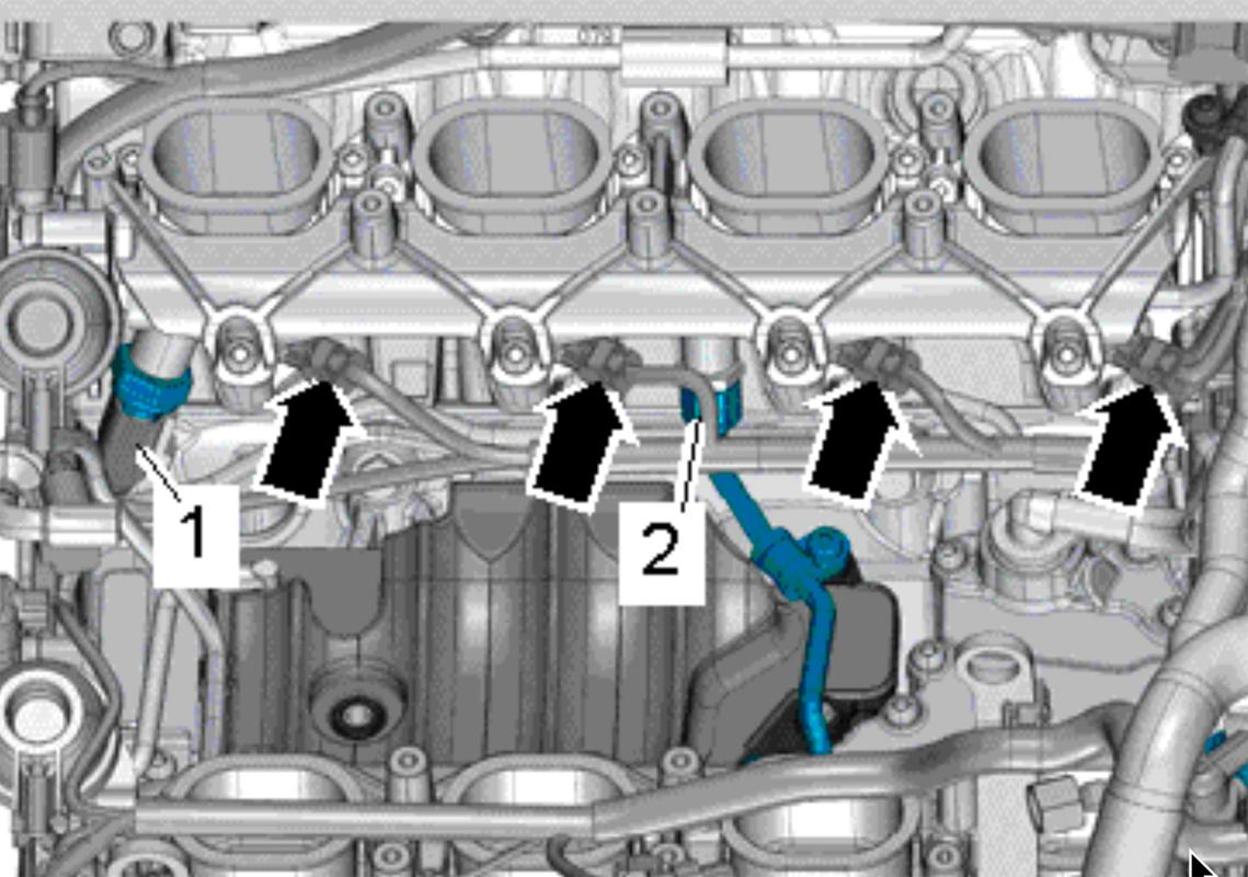
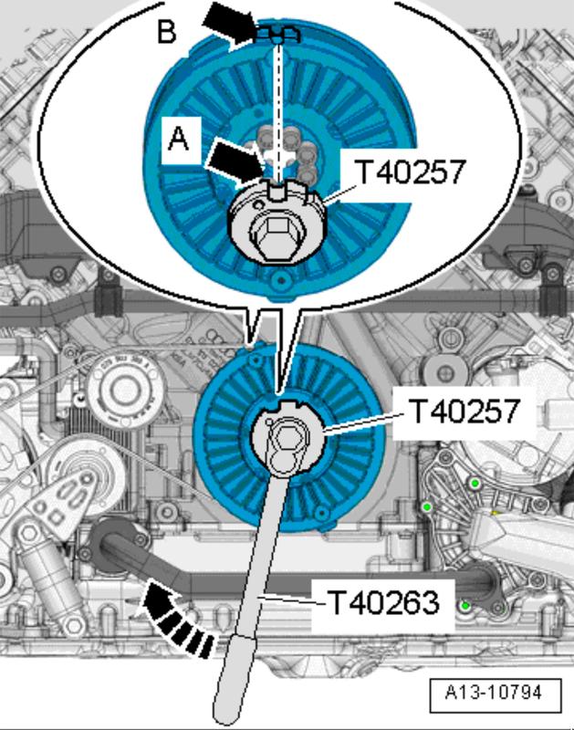
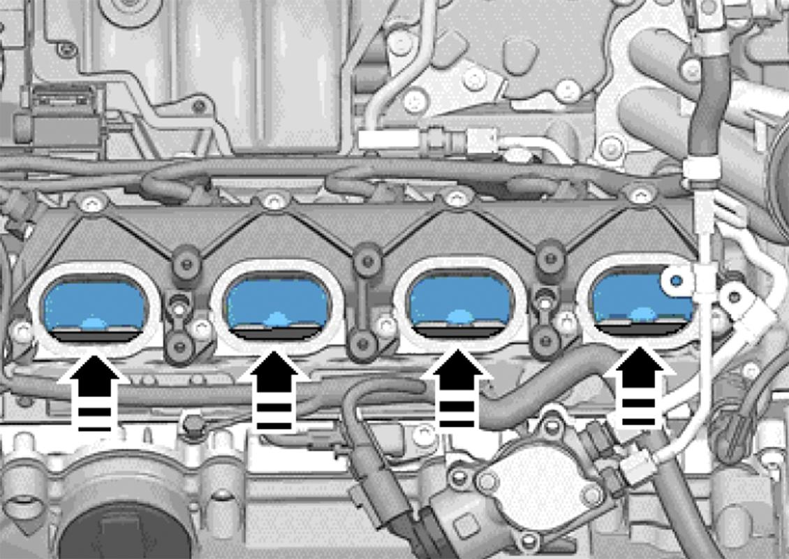
Here’s the photo from the FSM. The arrows are the throttle body (throttle valve) connectors and the 1 & 2, in blue are the evaporation hoses which must also come off.

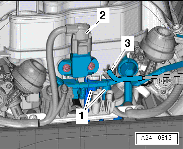
Real life, passenger’s side. The plug on the driver’s side is inboard, not on the outboard side. It is quite hard to get to and disconnect so be patient with it.

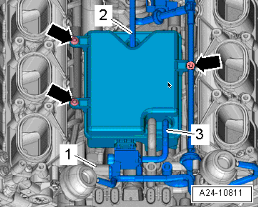
Most of the connectors are on the back of the intake manifold but there are some on the front. Looking at the FSM diagram, #1 are two vacuum lines that come off fairly easy. #2 is the MAP sensor plug and #3 is another vacuum line. Disconnect all of them. #1 is under the manifold and you can pull them off as you lift the UIM up.

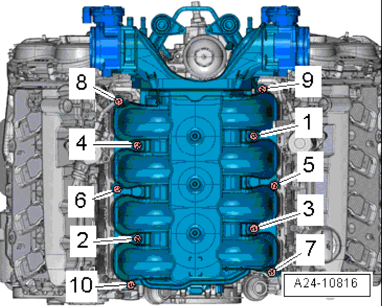
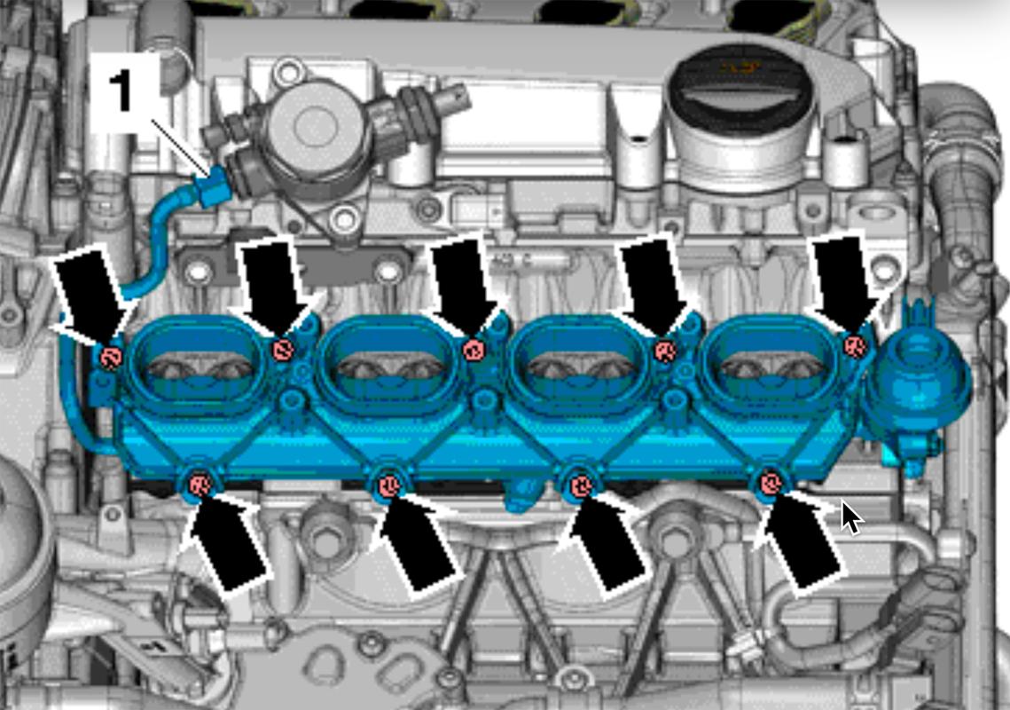
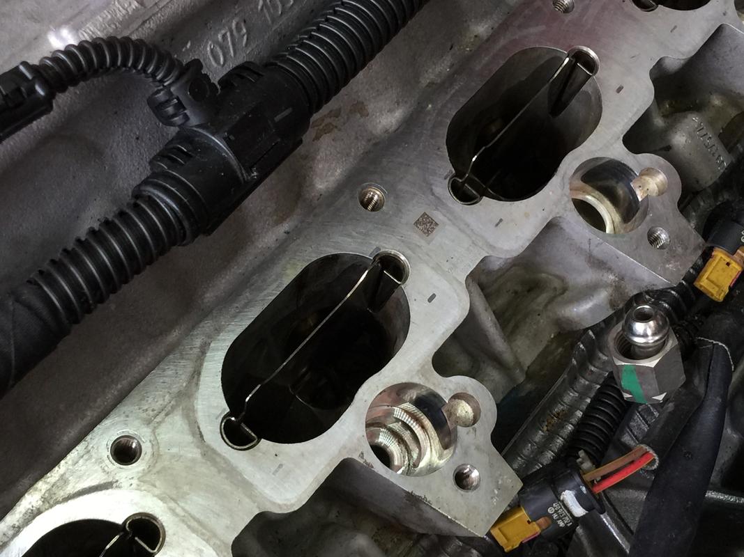
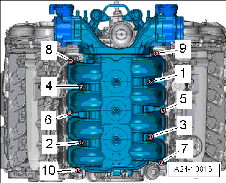
With all the lines disconnected, it’s time to remove the ten UIM bolts (T30 Torx) which secure it to the two lower intake manifolds (one for each bank). Loosen them in a cross pattern, 1-10 as listed below. THIS IS VERY IMPORTANT. DO NOT REMOVE THE METAL GROMMET BELOW THE BOLTS. LEAVE THEM IN PLACE.

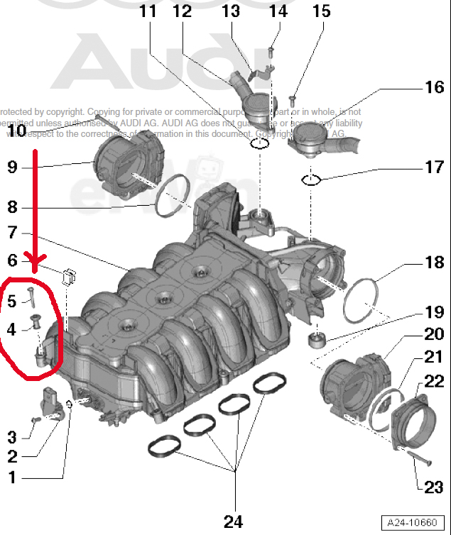
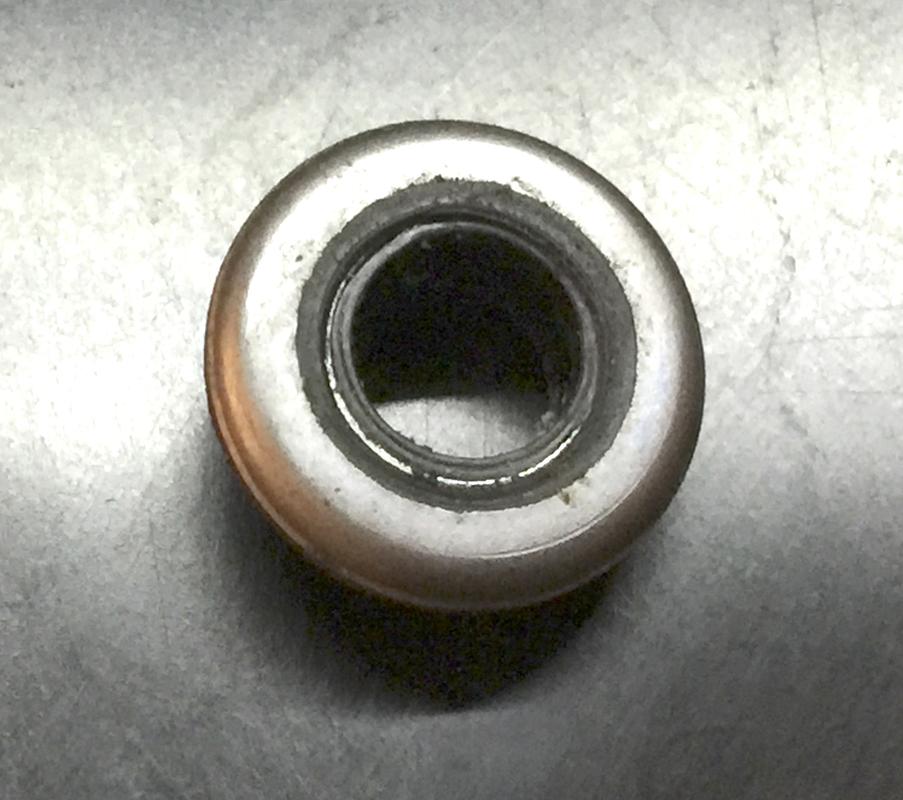
Pay careful attention. I’ve circled #4 and #5 in the diagram below. Five is the bolt. #4 is actually two pieces. One is the metal/rubber grommet visible underneath the bolts you just removed. The second is a metal spacer with a lip on one end. Due to that lip, it cannot be lifted out the top. It’ll only come out the bottom. If you remove all the grommets and lift the intake manifold up, those ten small tubular spacers will go tumbling every which way into the engine’s vee and perhaps further, never to be seen again. Leave the grommet in place. In fact, before removing the UIM, inspect each one closely and if need be, seat the grommet even further by pushing down on it so it’s fully engaged with the spacer.

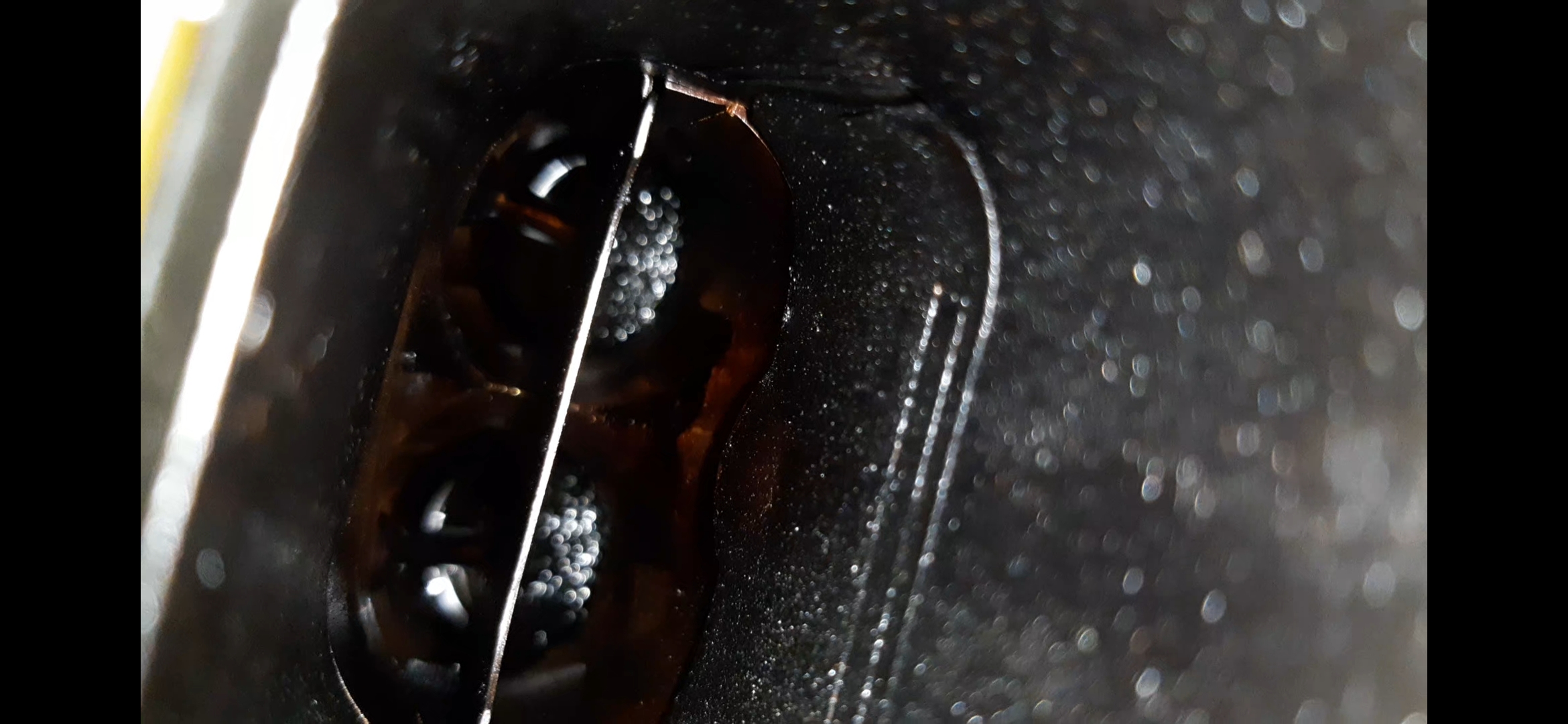
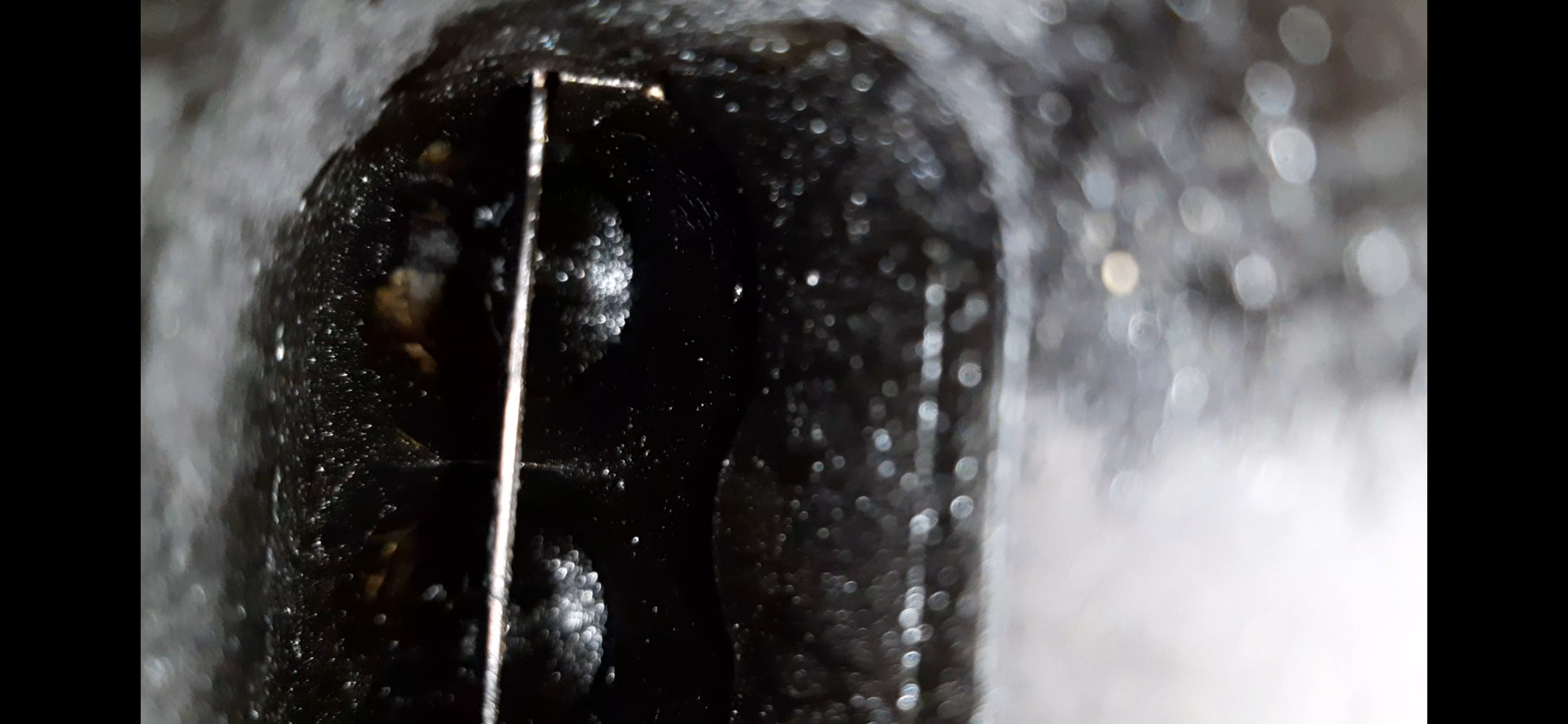
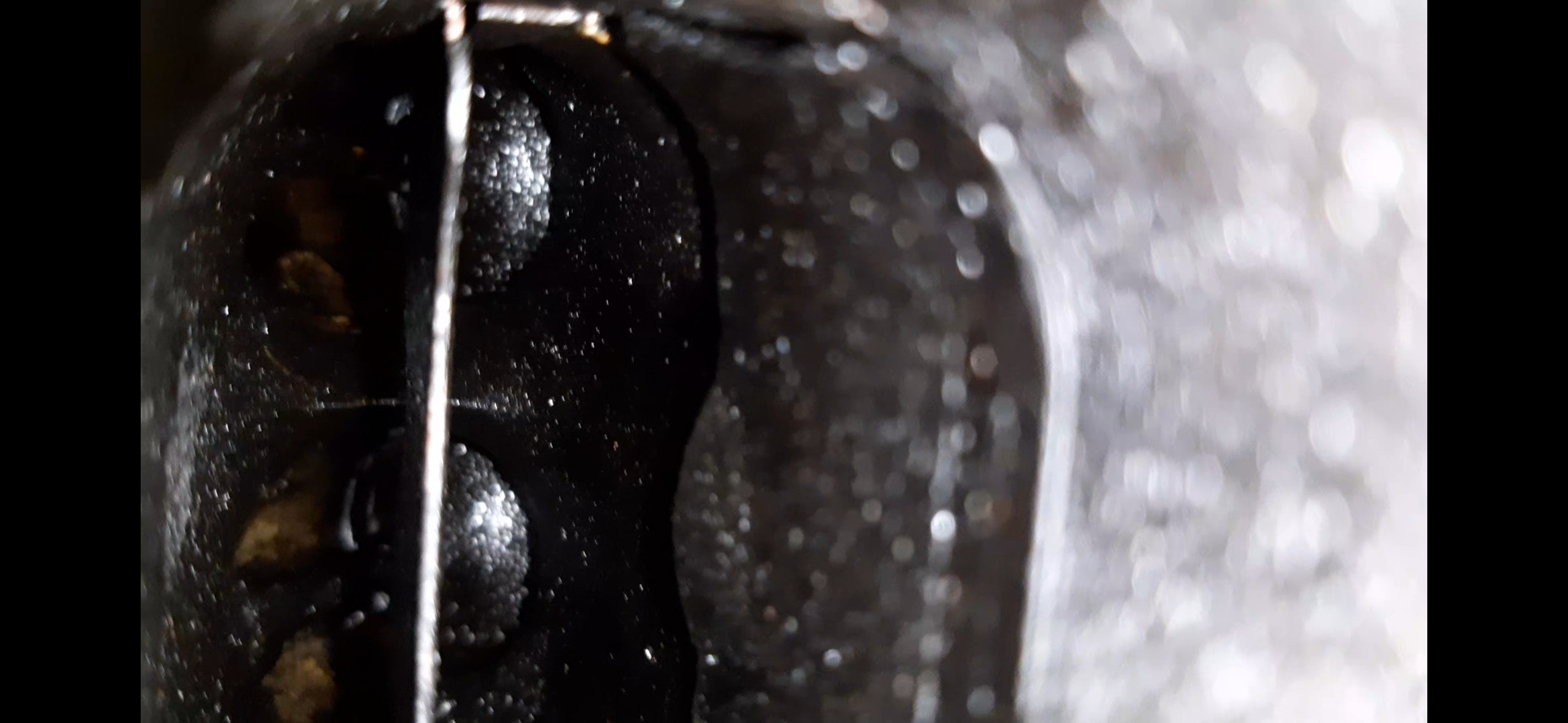
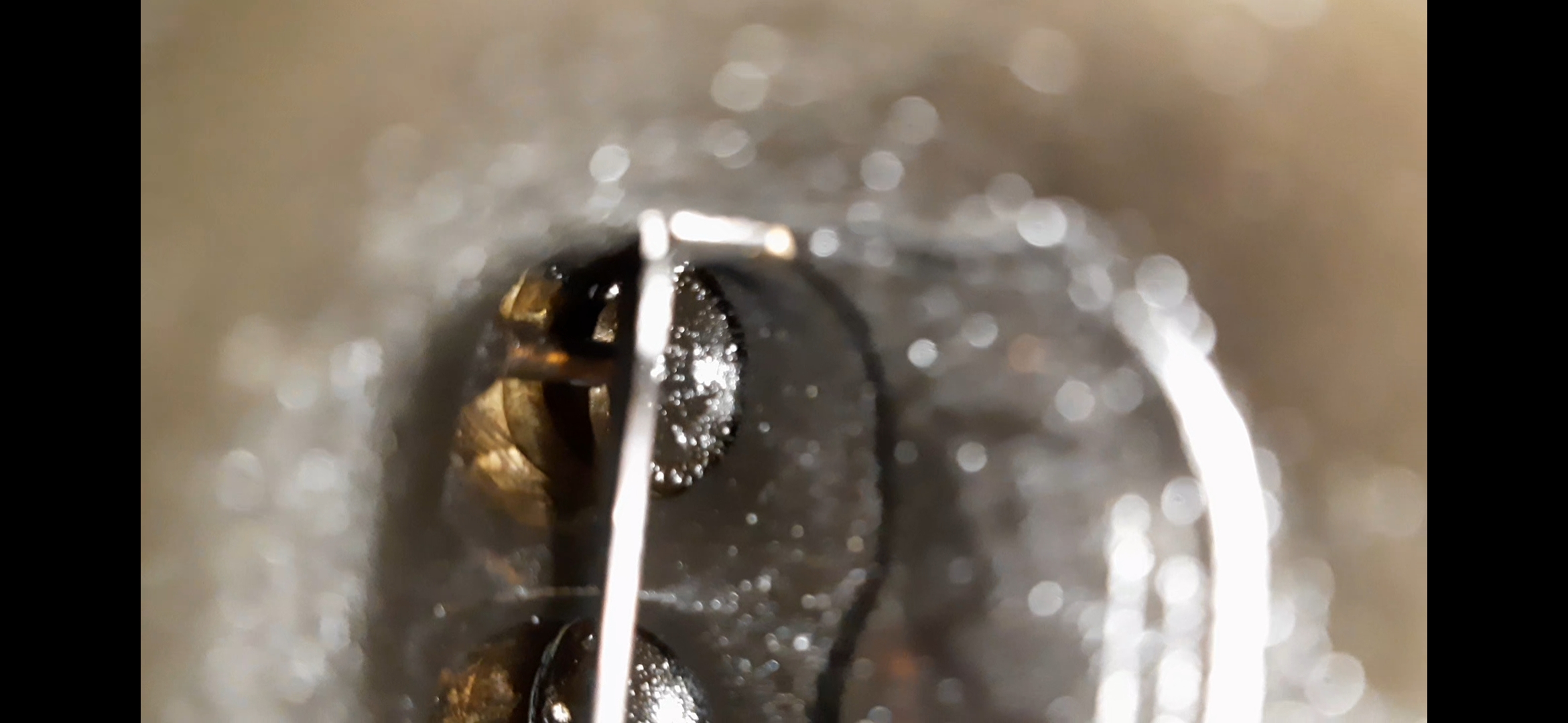
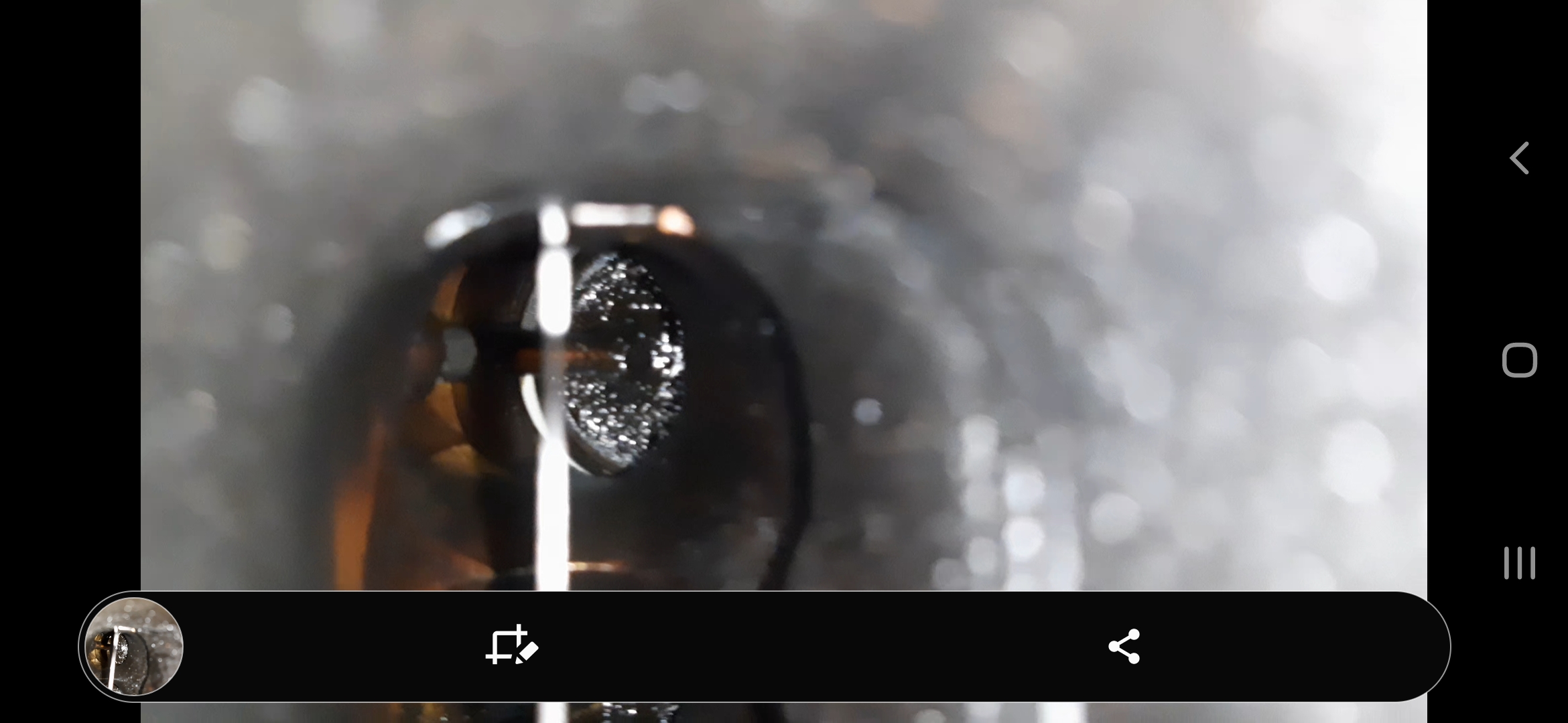
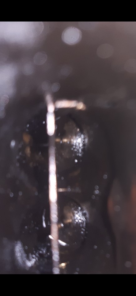
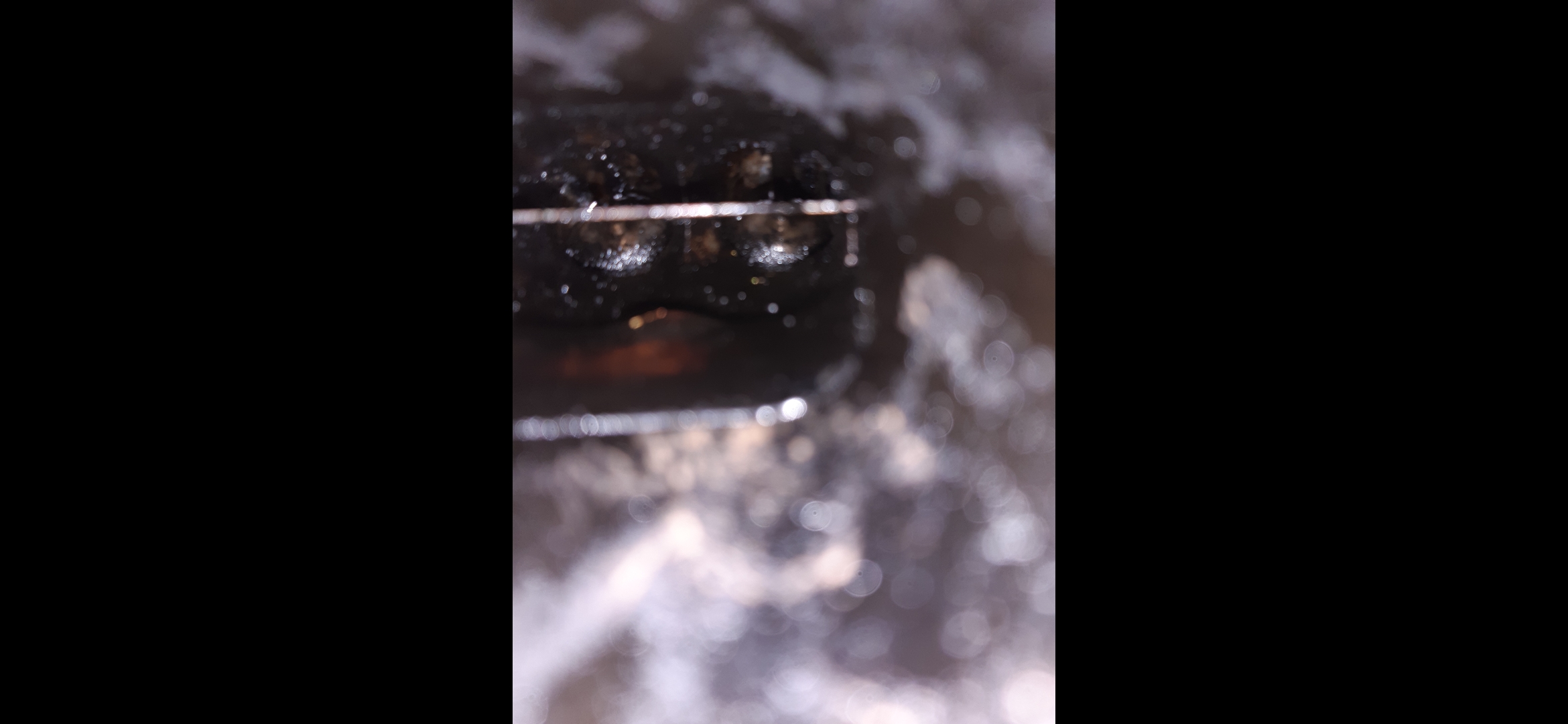
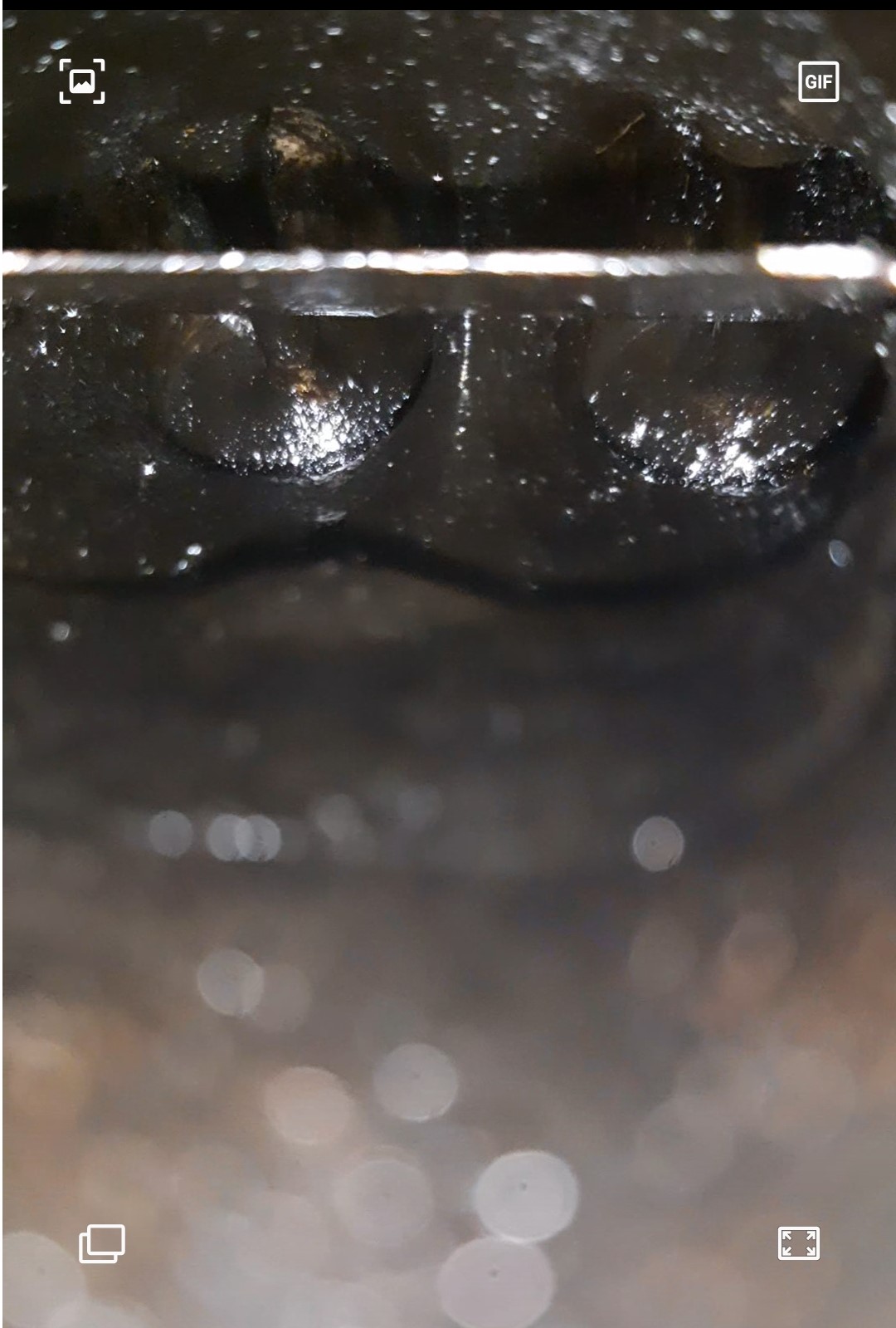
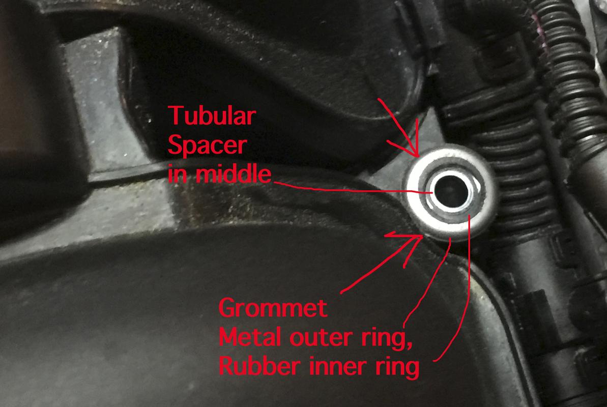
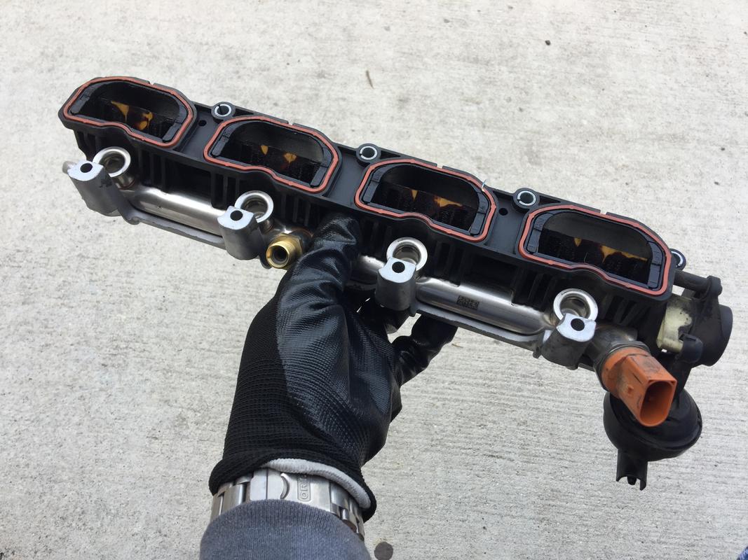
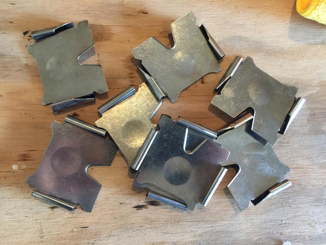
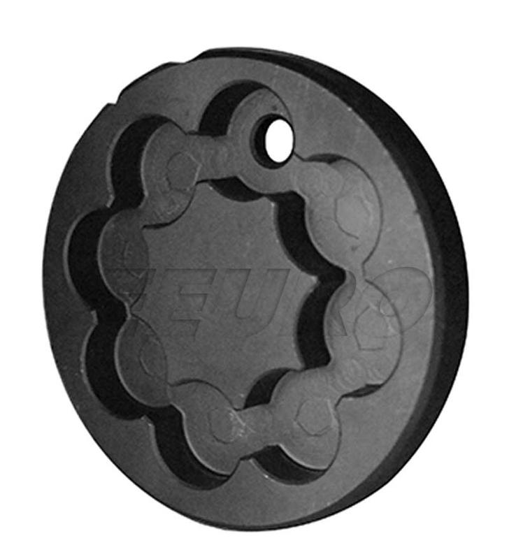
Here’s a photo of the grommet with the spacer still installed on the UIM. The second photo is a closeup of just the grommet. Note the middle is rubber and is what “grabs” the spacer and holds it in place. No, it’s not very secure which is why you need to make sure it’s fully seated around the spacer.

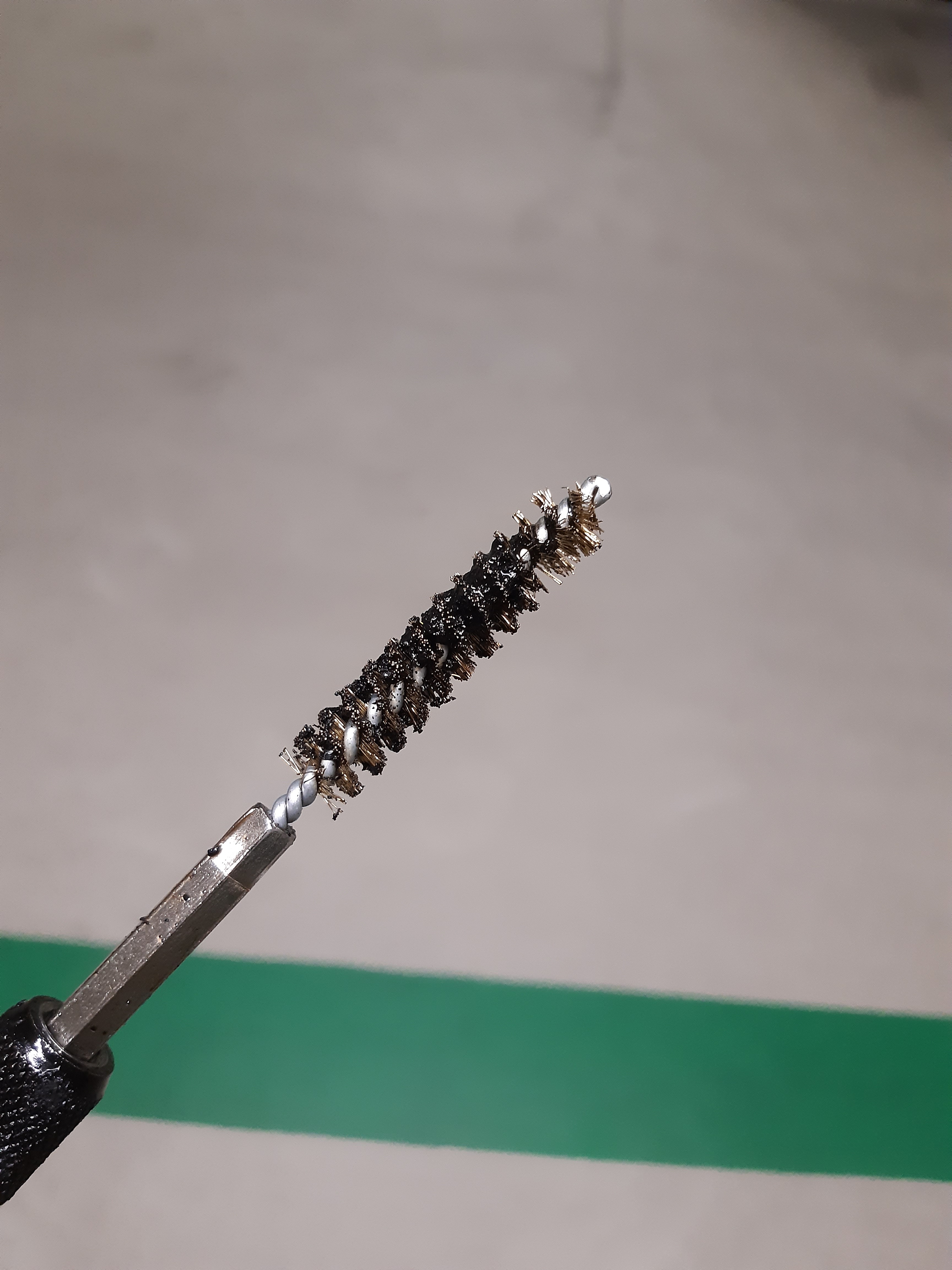
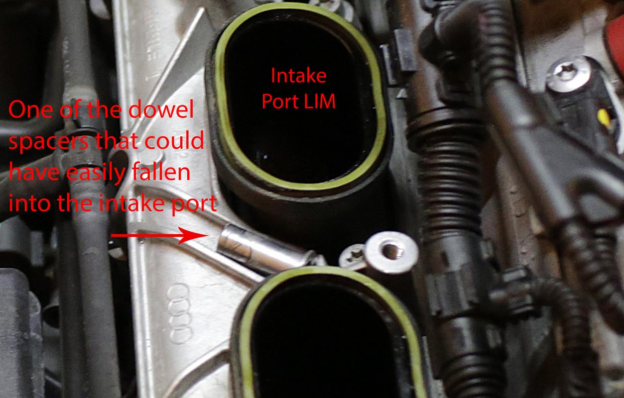
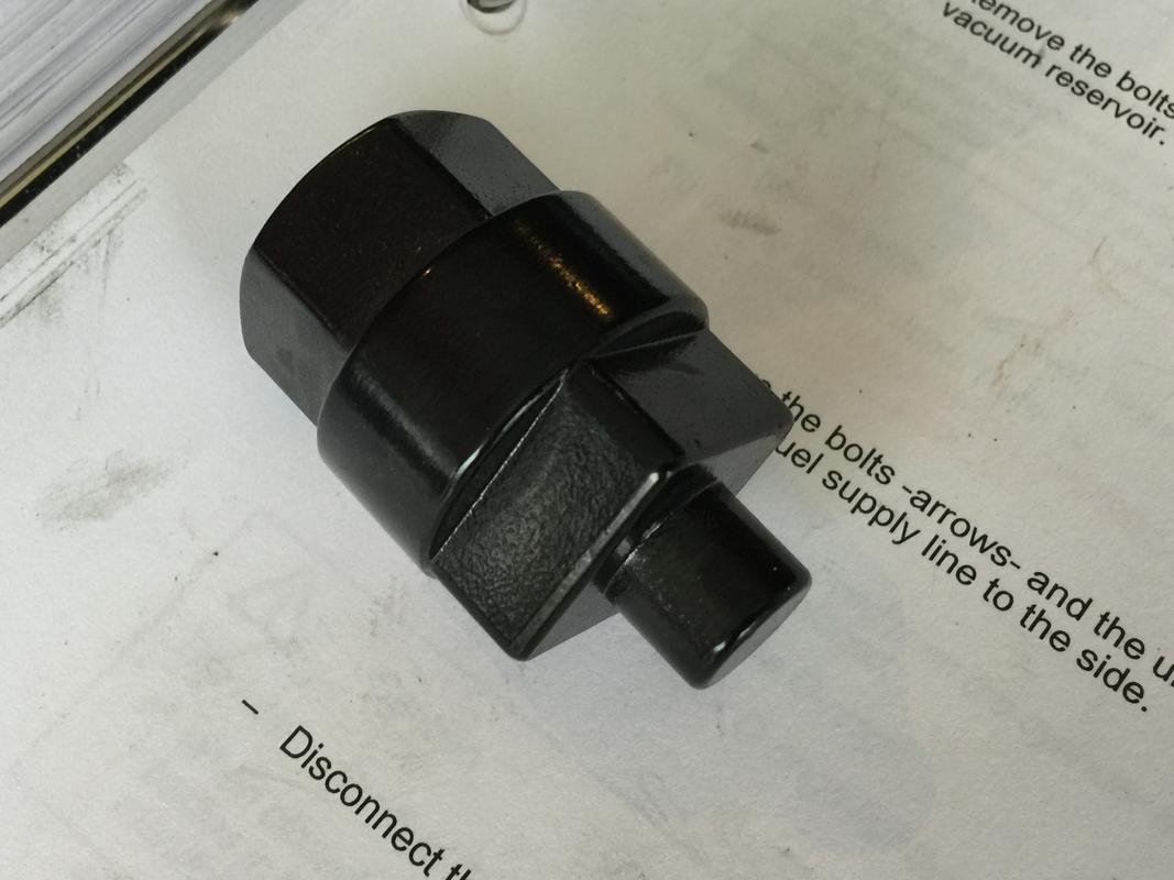
Here’s an UIM dowel spacer that fell very close to an intake port

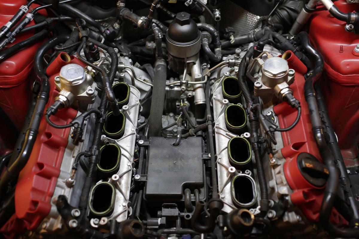
Once all ten bolts are removed, look over all the connections and make sure you have anything necessary removed. It’ll take a bit of force to separate the upper from the lower as the gaskets “seal” with heat. So it’ll come off suddenly. Be prepared. Once you’re able to separate it from the LIM, double check everything is disconnected. The harness on either side of the UIM will prevent the manifold from lifting up so you’ll have to wiggle the UIM up and out from underneath the harness, the engine hoist bracket and a few lines. If you haven’t disconnected the vacuum lines at the front/underneath the UIM, do so now that you have more space. And watch the spacers/grommets! If one falls off, at the very least, listen and look to see where it goes. If it falls into the valley, you’ll be removing enough that you’ll be able to find them down there.

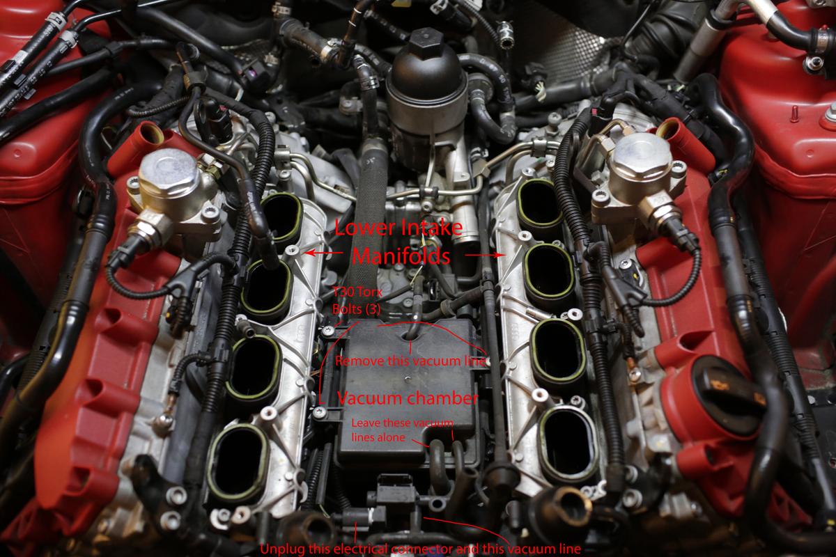
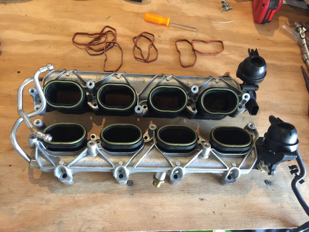
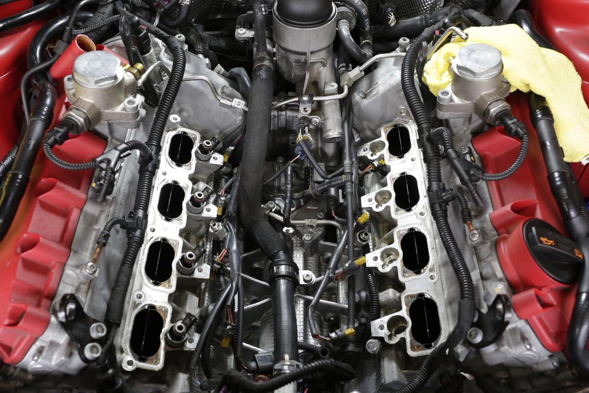
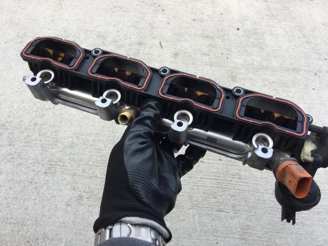
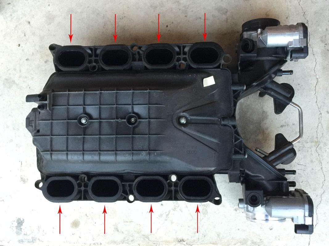
You’ll be left with this;

Lower Intake Manifold Removal

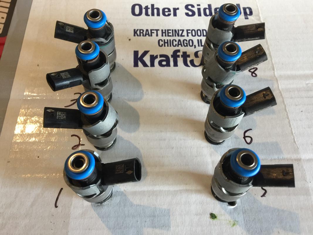
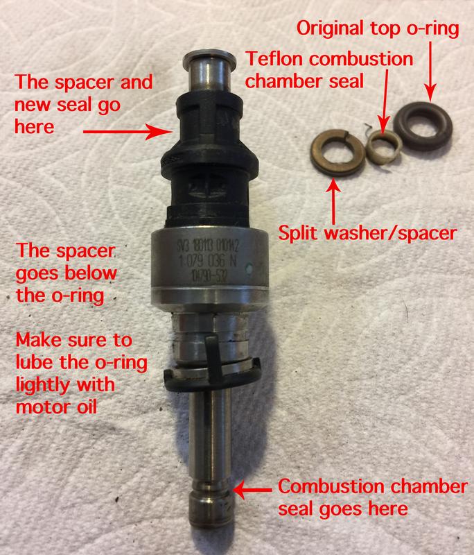
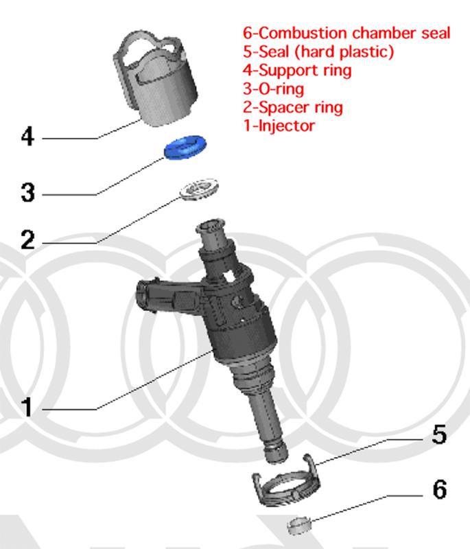
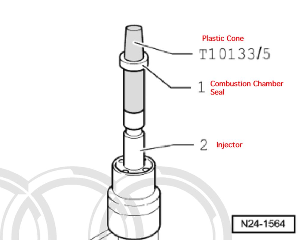
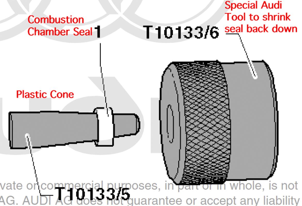
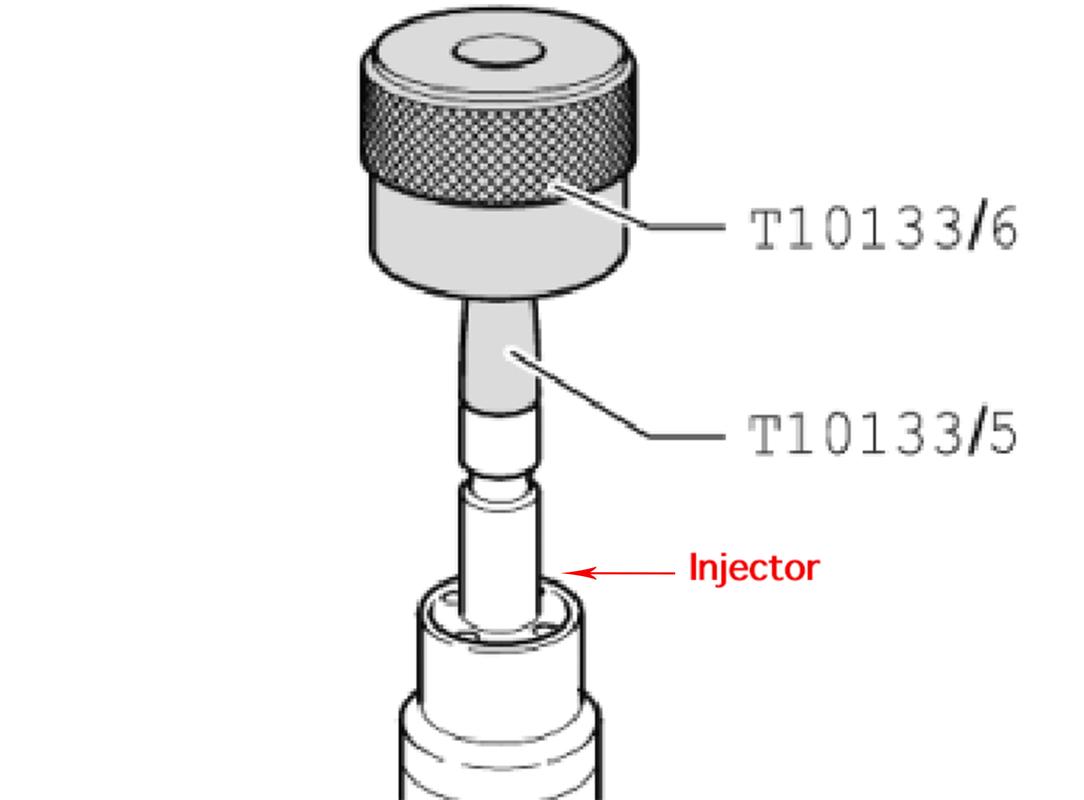
The LIM is difficult to remove for one reason alone; the injectors. Mine were “stuck” in the LIM fuel rail and as such, when I pulled either side up, no matter how I tried, the injectors would go with them. No way around it. With 50K on the clock, those OEM o-rings had pretty much sealed themselves to the injector bungs.

If you’re prepared for the above with rebuild kits for all eight injectors, it’s relatively straightforward. It still necessitates a good deal of force to pull each LIM up and off the heads. Keep that in mind.

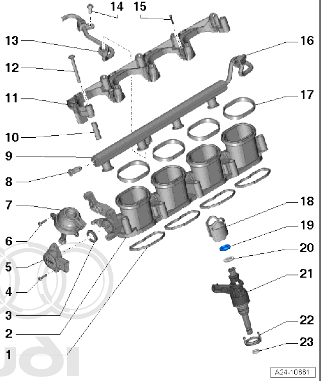
Here’s an exploded view of the LIM. Note, ALL of this comes up together as one piece except for the fuel return line (#13)

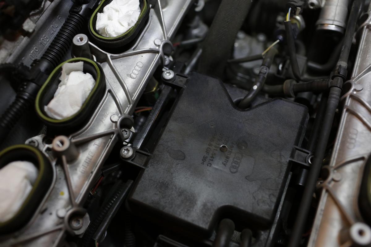
We’ll need to remove the vacuum chamber in the vee of the engine. It’s held on by three (two on the left, one on the right) T30 bolts to a bracket. You’ll only need to remove two vacuum lines; the smaller one coming off the top of the chamber nearest the rear of the engine as well as one connected to the front via a solenoid. You’ll need to unplug the solenoid as well.

Closeup shots of the bracket it’s bolted to. Note how it’s situated when you remove the vacuum chamber.
Driver’s side

Passenger’s side

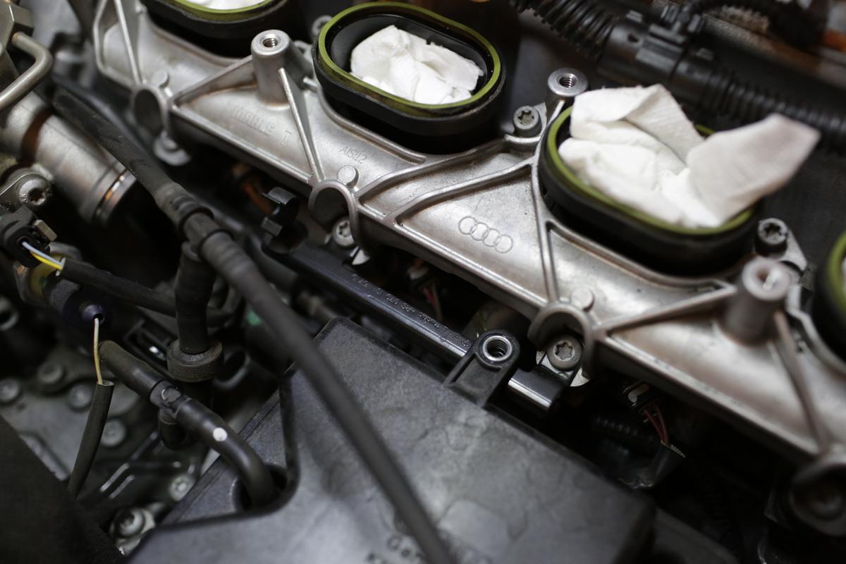
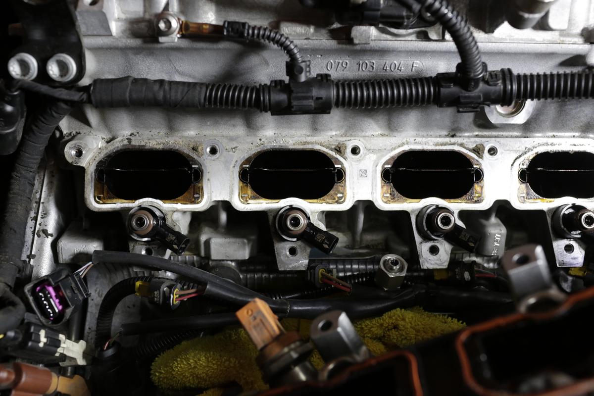
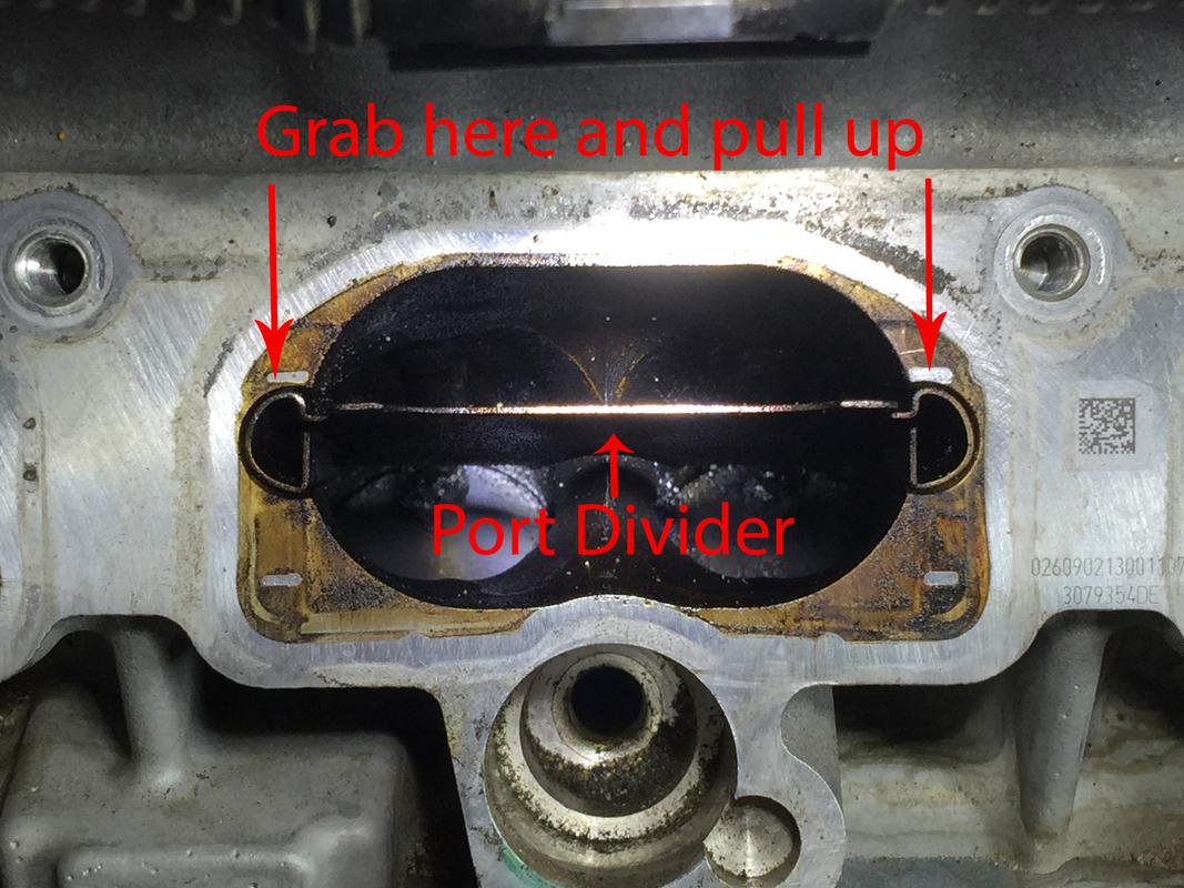
With the vacuum chamber removed, this is what you’ll see. Now is a good time to fish out those dowel spacers if you dropped any in the valley.

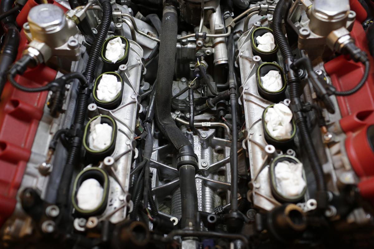
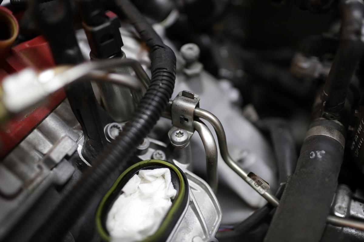
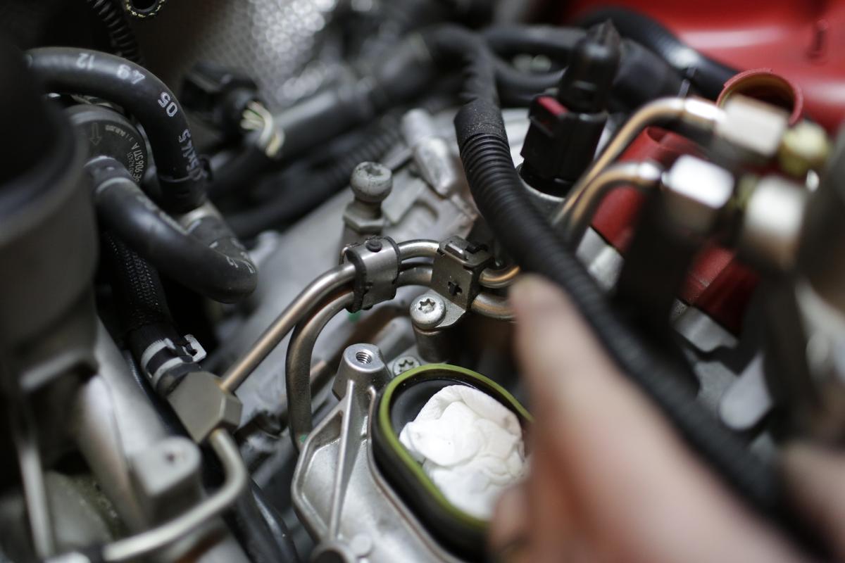
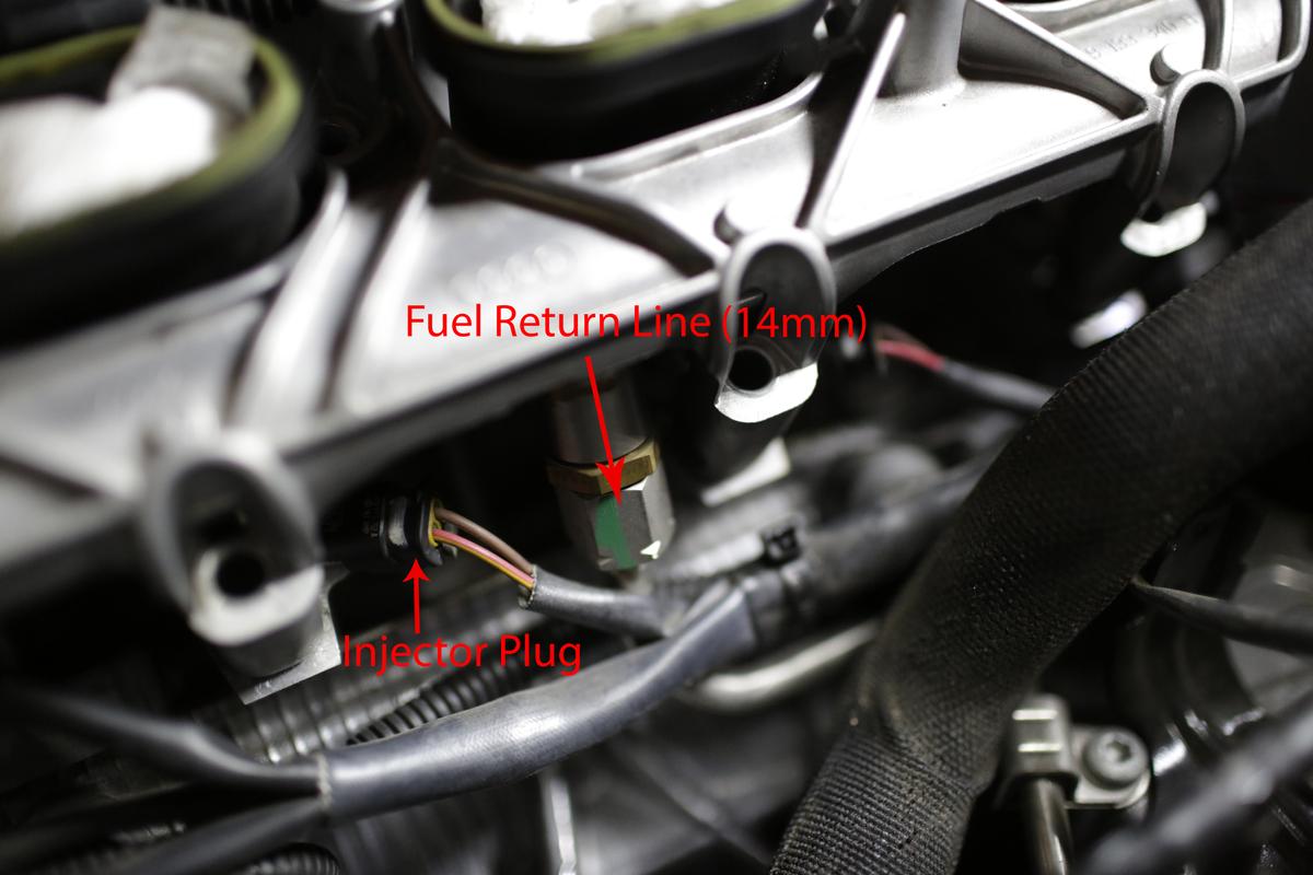
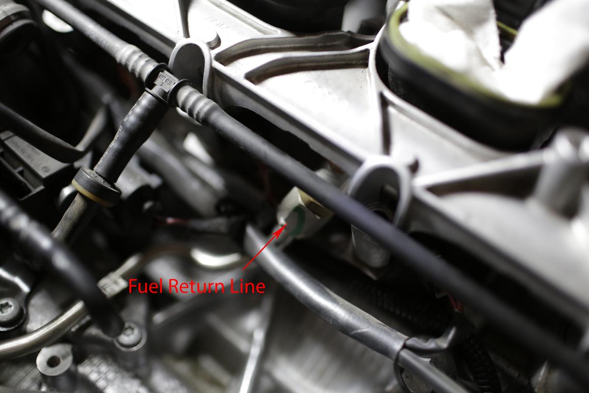
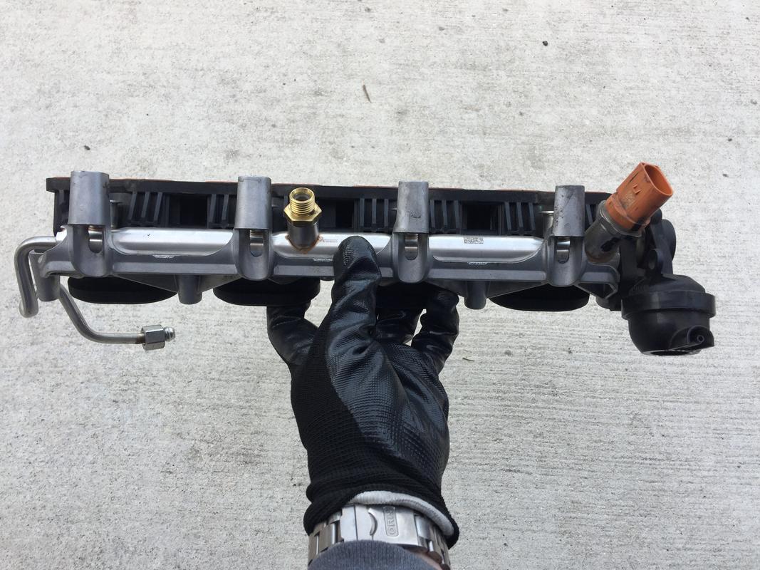
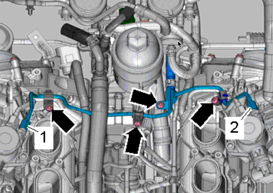
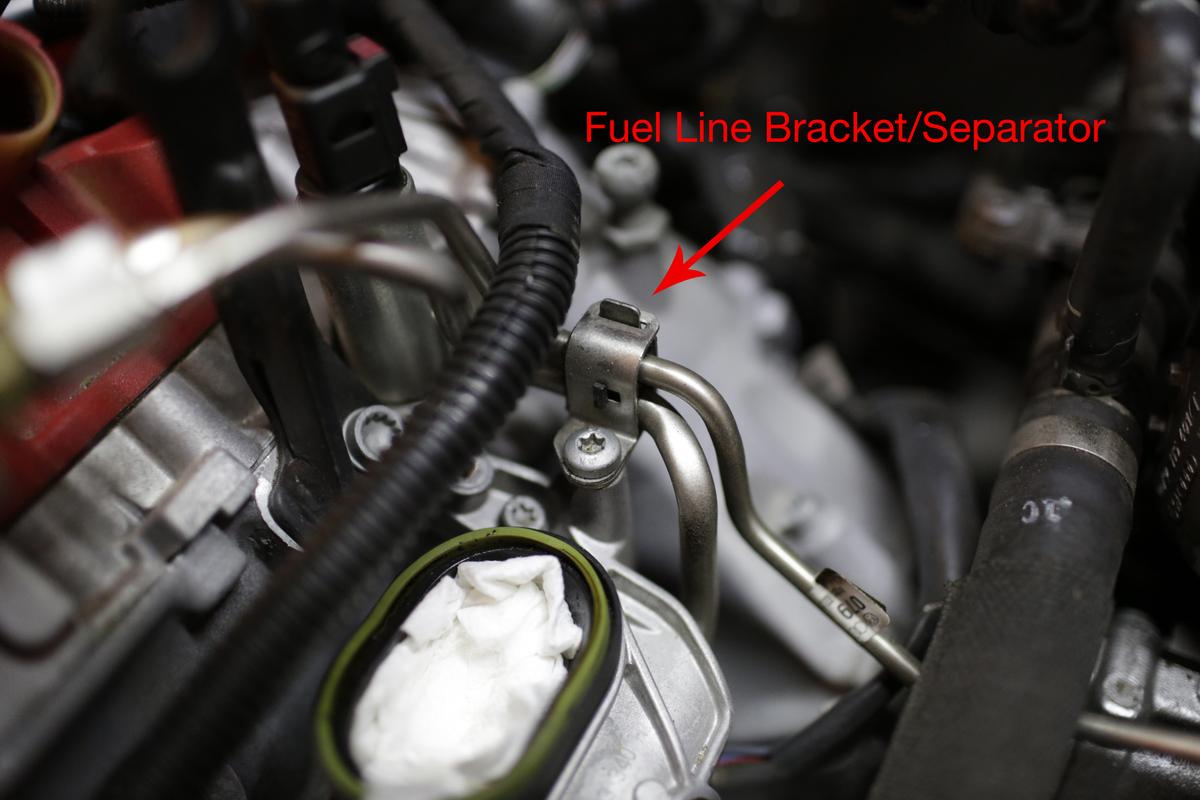
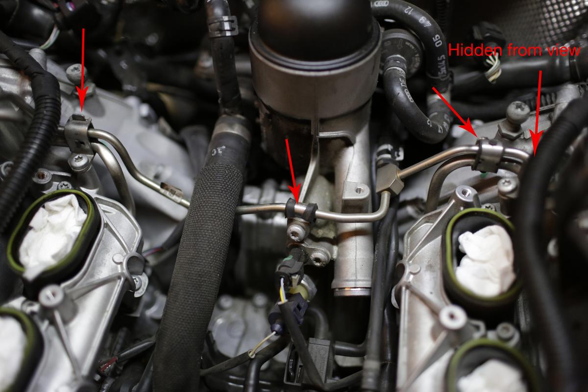
Take lots of photos and notice how the fuel line spacers are situated and where.

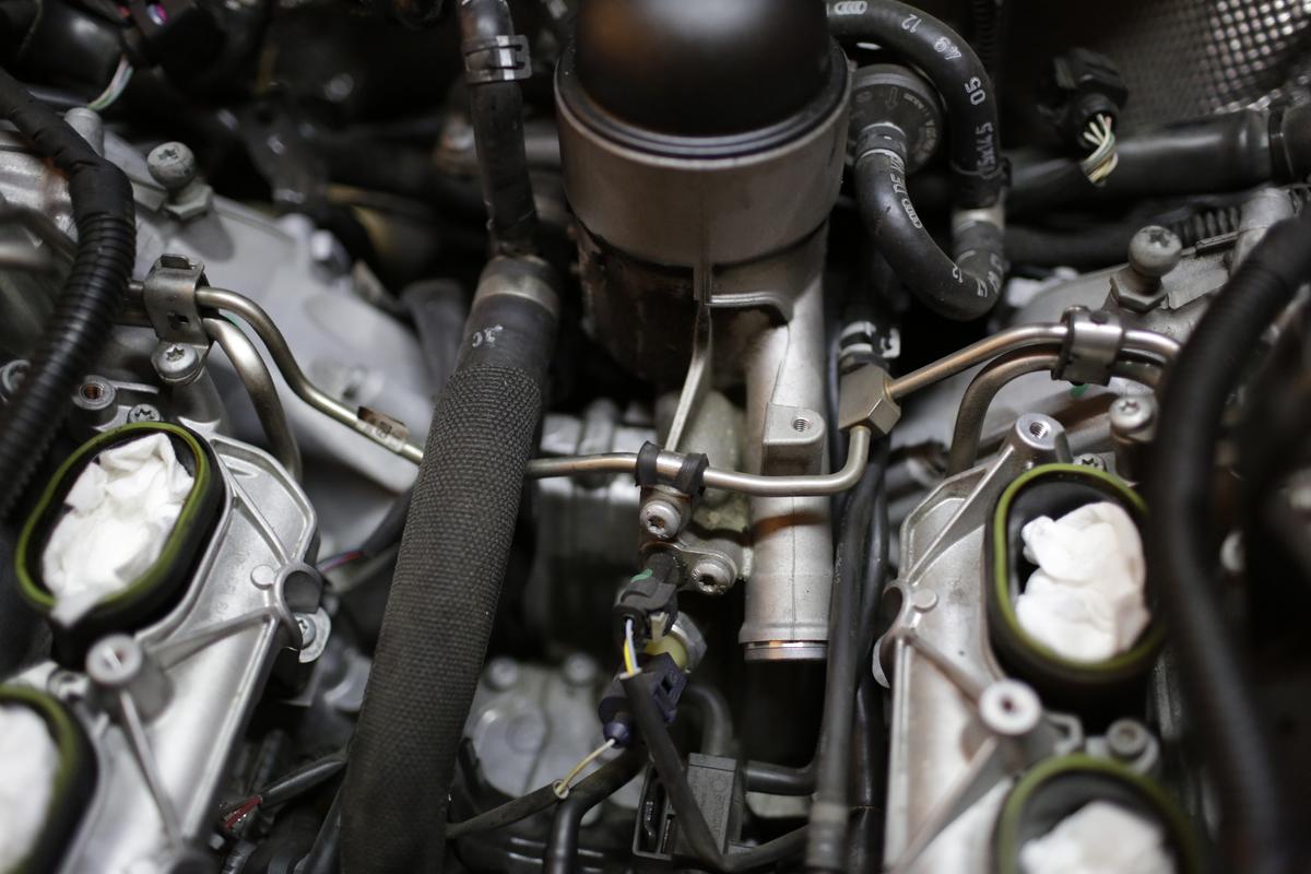
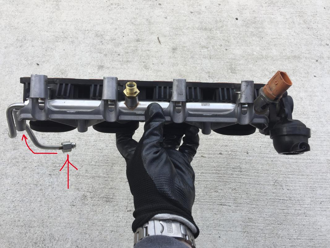
Remove both fuel return lines. Make sure to stuff plenty of rags underneath to absorb the fuel that will spill out. There’s one for each bank and if I remember correctly, they were 14mm (or 17mm) nuts. They’re not on tight and you can mark them with a sharpie to make things easier and not over tighten them when it’s time to reassemble everything. It’ll make it easier if you unplug all of the injector plugs prior. Note the passenger’s side injector plugs point towards the rear and the driver’s side towards the front.

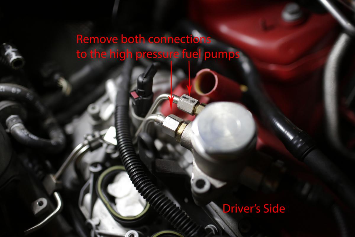
Remove the high pressure fuel pump lines. Stuff a rag underneath although I did not have any fuel come out of mine. Again, mark the nut with a sharpie so you don’t over tighten them. There’s two lines on each side. Once those are loosened, remove all the fuel line brackets pictured earlier to give you wiggle room.

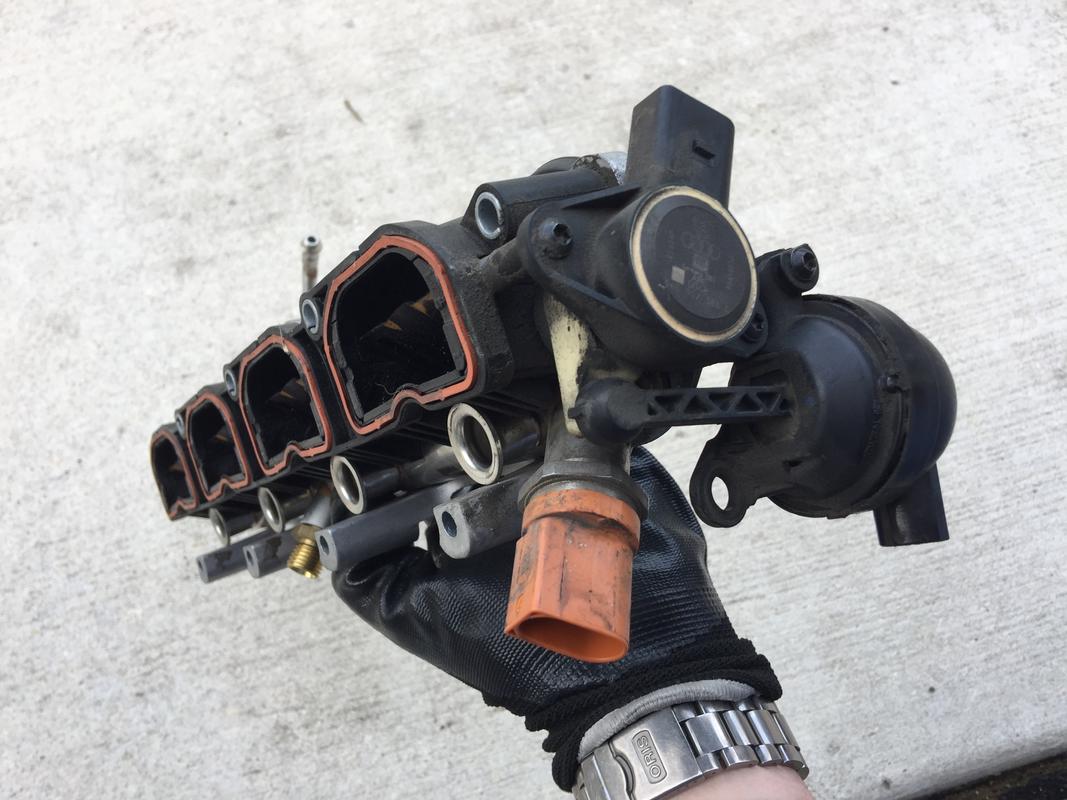
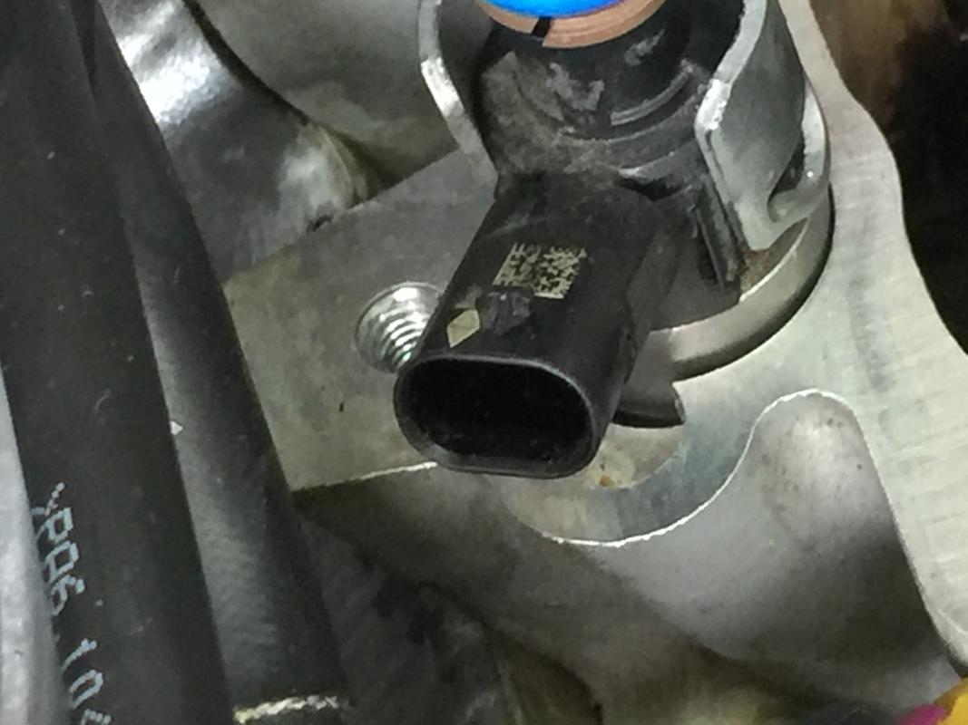
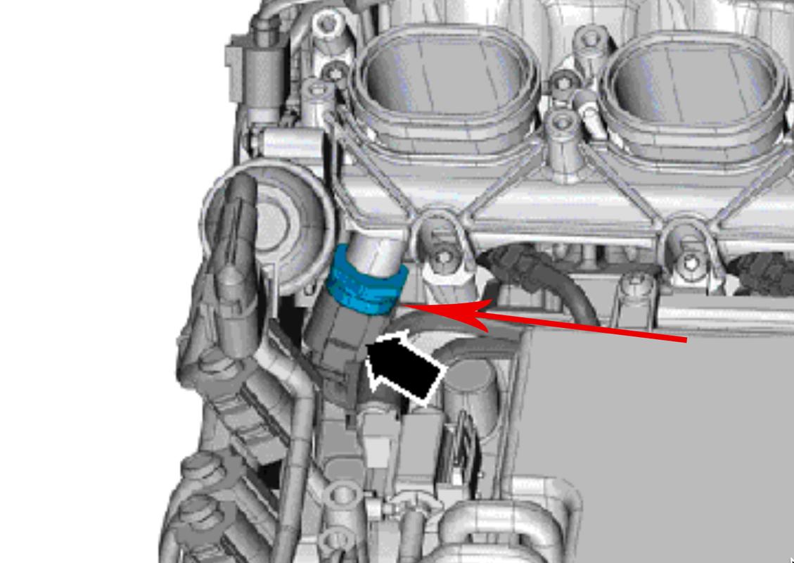
There are several electrical connectors on the passenger’s side LIM towards the front which need disconnecting including the fuel pressure sender pictured below as well as one on the vacuum actuator for the intake runner flapper system.

There’s one matching electrical plug on the driver’s side near vacuum actuator for the flaps which needs removing. It’s number 5 in the exploded diagram. One on each bank.

With all of the connections removed, it’s time to remove the bolts holding the LIM to the head. You’ll be removing them in a cross pattern. The top side bolts are longer and have a different head shape from the bolts along the bottom. Make mental note. Both are T30.

With the bolts, fuel lines and electrical connectors removed, grab the LIM by either end and lift straight up. You may need to use a small side-to-side wiggle motion to gently rock the injectors loose from either the fuel rail bung or from the injector ports in the head. You may get lucky and not all of them will come out. It will take a good deal of force!

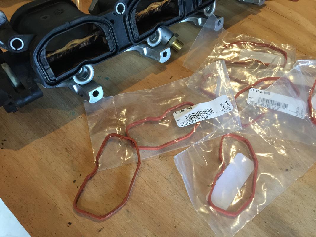
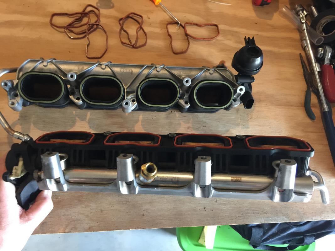
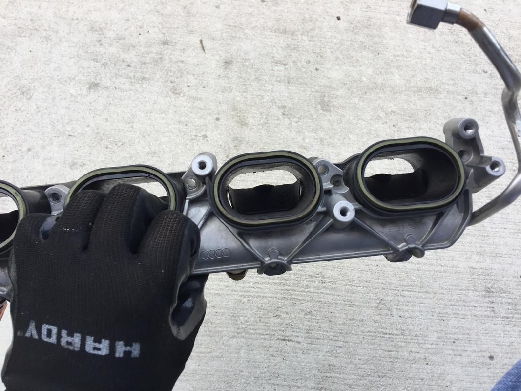
Shot of both LIM’s after removal. Old LIM to head gaskets pictured in background. The yellow/green gaskets up top are also replaceable but extremely expensive. Don’t damage them. They’re like $25 each. Ridiculous. FSM says to replace but they’re fine to reuse.

Closeup of one bank after the LIM was removed. The injectors are still in there but they did come up slightly, enough that I knew I’d need to replace the seals.

Overall of the engine valley with the LIM removed.

The next step is to remove all eight of the port dividers in the intake runner. Just use a pair of thin or needle nose pliers. Grab each side by the “D” shape, wiggling the divider and going from one side to the other as you pull up. Pull all of them and soak in some sort of carb or carbon cleaner. You’ll clean them off and reuse them. The protruding dimple faces down when you go to reinsert them back into the intake runners…

I took the injectors and punched holes in a cardboard box, labeling each injector so I know which one goes where. No real “need” to do this but what the heck. The new gaskets are already on (top o-rings are blue in the rebuild kit, the originals were brown).

New LIM to head gaskets but more on that later.

Gratuitous shots of the LIM just because. How often do you actually see them?


Dividers cleaned and ready to be installed after the carbon cleaning.

Carbon Cleaning
I know this is the step you’ve been waiting for. In the photo below, I’ve taped everything off except the port I’m cleaning. Additionally, I laid drop cloth in all four directions. In the end, the drop cloth, if you’re careful, isn’t necessary.

IT IS necessary to tape off the ports you’re not cleaning and TAPE OFF THE INJECTOR PORTS TOO!

After I was done cleaning a port, I’d tape it back over and mark the tape with an X.

With the car in the service position, there’s enough room to get a 3/8" breaker bar down there. I’d originally purchased a specialty tool for Audi which supposedly fits in the crank’s snout. See pic.

Well, it does not fit. In fact, there’s nothing but a bored out cone in the center of the crank. No threads, nothing. Somehow I had the wrong adapter. What you actually need is part number T40257 which fits over all the harmonic damper bolts. Here’s one place to get it but they’re on eBay as well; http://www.baumtools.com/shop/VW-Audi/13-Engine-Crankshaft-Pistons/T40257-VAG-Crank-Turning-Too#.XACeui3MzOY

I was in a pinch since I didn’t have the proper tool. The harmonic damper bolts are M8 triple square bolts. By inserting the bit in just one, you can easily turn the engine with the injectors removed. It was actually shocking how little friction there was. To be safe, I’d get the adapter. It’s like $35.

Shot from the FSM. Just ignore the arrows and other bit, just showing you how the adapter fits in there and what the crank end looks like.

Once you have your bit and breaker bar attached, rotate the crank until the valves in the cylinder of your choosing are closed. Just watch the valves aided by a flashlight as you rotate the crank slightly. It’ll be obvious when they’re closed and they’ll stay closed for a decent sized duration of crank rotation. Another little tip…usually one or two other ports are fully closed. This’ll save you time rotating the crank.

Test that they’re closed by putting a bit of gas in the port with a syringe, carb cleaner even. If, after a minute or two, the gas is still in there, you can begin carbon cleaning with the walnut shells.

My logistical modus operandi was as follows:
-Blast with walnut shells moving the nozzle around to try and get all areas of the port.
-Flip the adapter 180 degrees and repeat.
-Remove the adapter and inspect
-Go over the ports and valves with the picks, loosening carbon that’s stuck in the crevices of the valve seat as well as behind the valve guides (two worst spots)
-Put the adapter on, switch to the air nozzle, blow compressed air in and suck the chunks out
-Blast again, repeating the 180 degree rotation
-Pick at everything again, blow out with compressed air
-Blast once more and then blow out with compressed air
-Spray in carb cleaner (not carbon deposit cleaner) and wipe the ports out with disposable paper towels. Rinse and repeat until the runner walls and valves shine.
-Tape the port back over, mark with an X and move on to the next one.

Here’s a short teaser video of what the process looks like
[video=youtube_share;zrbkQCK1EZc]https://youtu.be/zrbkQCK1EZc[/video]

Once you get through with carbon cleaning the ports, we’ll want to take several preparation step before reassembly.

Since the injectors are out, the injector ports in the head need to be cleaned and spotless. There is a factory service cleaning kit that you can probably track down or even purchase small diameter twisted wire nylon or soft brass brushes. A rifle (gun) cleaning kit also works. I bought mine at Walmart for about $7.

I did clean out the bores by shop vac and hand first to remove any grit. Using the brushes and carb cleaner left the injector port walls with a mirror finish. I also cleaned the smaller bore where the injector nose/seal sits.

Clean injector ports and the dividers reinstalled.

With the injector ports cleaned, plug them up with some paper towel so nothing falls in them. Make sure the rest of the mating surface between the head and where the lower intake manifold sits is completely clean. Wipe it down with your cleaner of choice and finish off with denatured alcohol. Spotless is ideal.

You can also re-install the port dividers. Remember, the dimpled protrusion goes on the down side.

To R&R the injectors, you’ll need the rebuild kit which consists of a new teflon seal, a top o-ring and a split ring shim. You can only buy them as a kit. Each kit contains these three elements so you’ll need eight kits. ECS does sell the kit. Alternatively, if you’re an Audi Club member, the 10% discount actually makes it a slightly less expensive alternative. My dealer does not stock the kits. I had to overnight them from the Fort Worth distribution center. It was an extra $14. Won’t break the bank but do plan ahead and have the kits prior to pulling the injectors. Worst case scenario, you can send back unused kits if you manage to have an injector or two that decide to stay put.

The kits. Note they’re made in Italy.

Here’s an injector prior to having the new kit put on. The original top o-ring is brown, the new are blue. The shim and the teflon seal look the same.

To get the old teflon seal off, use a small utility or hobby knife to simply cut them off. Be gentle as you don’t want to gouge the injector with the blade. The o-ring comes off easily with a small pick or even your fingers.

Here’s an exploded view of all the injector components from the FSM.

The tricky part to the injector rehab process is getting the teflon combustion chamber seal installed. The seal itself is malleable. It’ll stretch and you can also compress it. As it comes out of the package, the seal’s inside diameter is smaller than the outside diameter of the the injector’s tip. The seal sits in a groove with a smaller outside diameter than the shaft. To get the seal onto the injector, it needs to be expanded. The best way to do this is with a cone.

Here are some excerpts from the FSM using the specialty tool which costs about $200. I’d recommend purchasing the tool but it can be done without it if you’re careful and detail oriented.

First step, slide the seal onto the expansion cone.

Second step, push the seal onto the expansion cone further with other half of the audi tool using a twisting motion.

Third step, line up the expansion cone and twist with the other half of the Audi tool until the seal slides over the end of the injector and into the groove.

With the combustion chamber seal in the injector’s groove, continue to twist the tool and it’ll shrink the seal back down.

I had a bit of luck rigging up my own kit. I had an old brake bleeder I’d pulled out to use the vacuum pump to pull back the flappers on the LIM. It included a number of adapters designed to fit various hose sizes. The adapters were cones, made of a very hard, smooth plastic. It almost has a silky feel to it if that makes sense and a very low coefficient of friction. Since it was a long cone, I just cut it at the point where it was the same size as the end of the injector. Perfect! I also had a small plastic cylinder that was just the right size to push the seal on and expand it. Once you get to a certain point, you can actually do it with your digits. I wore clean latex gloves when handling the seals.

Here’s the cone I used, next to a guitar pick for size reference. Worked like a charm.

Now I did not take any photos of me shrinking the seals back down as it’s a two-hand, delicate job and I wanted to concentrate. I took a properly-sized zip tie (same width as the seal) and reversed it so the smooth side was on the inside. I shrank it down so that it still fit over the seal and then used a pair of pliers to press against the outside of the zip tie and worked my way around the outside of the seal. It won’t completely shrink back down but it was enough that the injectors went in easily (with a bit of pressure which is normal) and I’m not experiencing any issues.

I’m a sticker for doing things the right way and I honestly recommend getting the tool. I was in a bind, not knowing how easily the injectors come out and it caught me unprepared. Live and learn. There were enough people online that do it with the zip tie method that I felt comfortable doing it that way.

One you have the injectors rehabbed, insert them back into the injector bores. DO NOT PUT ANY LUBE ON THE INJECTORS! NOTHING ON THE TEFLON COMBUSTION CHAMBER SEALS. VERY IMPORTANT!

The injectors should slide in 80% of the way and it’ll require a bit of careful force to push them in all the way. Be gentle. Take careful note of the cutout in the head for the injector electrical connector and make sure it’s oriented in the right direction before trying to push it all the way in the bore.

Closeup of an injector almost seated in the bore. Find a socket that sits flush with the support ring and use a rubber mallet to softly tap the injector in place.

LIM Reinstallation
With everything clean and the injectors in place, it’s time to reinstall the LIM. Make sure you’ve lubed the injector o-rings. I also put a thin coat on the injector bungs in the lower intake manifold.

You’ll want to clean out the LIM runners and flappers a bit as they can become caked with oil over time and stick open/closed. Clean them and then make sure they’re functioning properly with the vacuum pump. Clean the green, LIM to UIM gaskets on top with denatured alcohol.

The last thing you’ll want to do before installation is install the new LIM to head gaskets. They’re the red ones on the bottom. They’re stuck in there somewhat but they come out fairly easy with a small pick. Install the new ones by pressing them into place and you’re good to go.

With the injector o-rings lubed, position the LIM and line up the injector bungs in the LIM with the top of the injectors. Before you press down, make sure the high pressure fuel line nuts are up where they should be. They can slide all the way down to the LIM and get pinned between the LIM an the block.

Attach the vacuum pump and open the flaps fully.

With everything lined up, push down on the LIM until the bottom sits firmly on the head. Slip the nine bolts into their respective homes, the long bolts on top, the shorter, button head bolts on the bottom.

The tightening sequence is in a diagonal pattern in stages up to 9Nm.

At this point there are no real gotchas except for the spacer/grommets on the upper intake manifold. Just take it slow as you put everything back in place. The vacuum hoses are all shaped so it’s fairly obvious where they go.

With both LIM’s in place, make sure all the fuel lines are routed correctly and loosely place the fuel line separators around the fuel lines and bolt them down loosely so you can still move everything if needed. Once you have everything installed where it should be, tighten the fuel fittings. These include the return line on the bottom of the LIM (both sides) and two on each high pressure fuel pump. You do not have to crank them. In fact, do NOT crank them. Torque all of the fuel fittings to 25Nm (18ft. pounds). That ain’t much.

With the fuel lines tightened, bolt all of the fuel line separator brackets down securely. There’s four of them.


Plug the injectors in as well as all of the electrical fittings you can reach now and probably not later. This includes the fuel pressure sensor, passenger’s side at the front side of the rail. It’s easy to miss and/or forget.

With all of the electrical fittings in place, re-install the brackets for the vacuum chamber. If you’ve forgotten which way they go, take the two brackets (one on each LIM) and the vacuum reservoir and line everything up. It’ll be obvious which way they go in as the vacuum chamber sits snugly in a space within the engine’s valley. Things can only go in one way.

With the brackets in place, line up the vacuum reservoir. Check to see which vacuum lines need to be plugged back in before fully securing.
Here’s a photo from earlier with the reservoir in place.

Check all the vacuum lines and electrical plugs at the front of the engine in between the two LIM banks. Make sure everything is attached properly otherwise you’ll be pulling the LIM again to find out what you left off. Not fun.

Check ALL the plugs and vacuum lines once more. Make sure everything is on securely. At this point we’re ready to re-install the UIM.

Torque specifications (two steps)
1-Tighten bolts 1-10 in order listed to 8Nm
2-Tighten bolts 1-10 in same order to 11Nm

First things first, clean the mating surface for each intake runner on the bottom of the UIM. You can use denatured alcohol. Resist ANY urge to unbolt the upper and lower portions of the upper intake manifold to see what’s inside. I have a feeling it’s sealed and those seals would not be easy to replace. So tempting though.

Torquing everything down correctly is the easy part. The hard part is getting it back in with all the spacers and grommets intact. I found the wiring loom running in between the heads and the intake manifold to cause interference. You’ll also need to loop the passenger’s side PCV hose back through the handle/support brace on the rear of the UIM after you get it semi-situated and in place.

With the spacers and grommets, just make sure they’re pressed in place good and tight and make a concerted effort to not bang the UIM on anything or jar it excessively. It’ll take some fiddling and patience but it will go in.

Be sure to plug in the driver’s side throttle body while you can still move the UIM around. Makes things much easier.

After installing the UIM, go over all of the various electrical, coolant, vacuum and PCV connections on the back of the manifold and make sure they’re securely attached and the clamps are all in the proper location. Do the same for the front of the UIM.

For what it’s worth, in this diagram, I never removed the #3 clamp which is the hose that loops around the UIM support bar. It’s easier to just snake it through everything.

Front vacuum connections.

Some of the connections on the rear.

Push the PCV pressure regulating valves back on and bolt them down to 4.5Nm. Re-attach the other end to the top of the valve cover.

With the UIM installed, and a bit of time on your hands, I’d suggest changing out the accessory belt.

1 Like

Ok this thread is now fully updated with all the photos and videos attached. Lemme know if anyone sees any issues.

Thanks For this Detailed DIY Ape!
It’s highly intimidating, this project and from the DIY. Especially since I had trouble with just the down pipes :joy:. I plan on getting this done soon so I’ll look into this page closer. The car is at 46k so maybe within the next 10/15k miles.

Yeah it’s a about that time for you. It isn’t super technically complicated but there is a lot that can go wrong so best to have someone else do it if you have doubts.

I do think I found a way to do this without putting the car into service position and using the starter to turn the motor over. Looking to see if I can wire a remote starter into the OEM harness where the starter button goes. They have a long enough lead that you can run it out the window and be looking down at the valves when you hit the button quickly to rotate the motor a bit. Just disconnect the fuel system (you pull the fuse on the LPFP anyway!) and you’re golden. Not quite as “exact” as using the crank tool and a breaker bar but the valves stay fully closed for a good deal of time during the crank rotation.

Well I have this Thread to refer to and I’ll need a bottle or 2 of “Focus Factor” tablets in addition to labeling every part if I decide.

Go for it i did and with Michel’s guide i got it done and its never missed a beat since, just take your time and label things and take photos to remind you of where things go and you’ll be fine.

Also Michel if you manage to work something out to rotate the crank via the start button let me know i would be interested in having one for my car :grin:

Will do. It’d require pulling up the center console and the starter button but it’d plug in and be FAR easier than putting the car in service position!

That’s great thank you Michel :blush: it will defo be easier than putting it into the service position and it will save time bonus !!

Our PCV valves seem to be powered by a stronger vacuum than that of for example the v8 S5 (completely different design). A wild guess is that Audi tried to mitigate the build-up. In other words I would ensure to have good working PCV valves. It does seem that cylinders 2-3 and to some extent 6-7 get the bulk of the PCV driven build up.

This leads me to conclude that preventative maintenance using spray cleans can also exponentially help alleviating the problem by removing the build-up that comes off easily but slows the airflow down. That will also cool down the valve head a bit more.

I was finally able to replace both PCV’s on my car. I made a guess as to which one was bad and guessed wrong sadly…even switching the “good” diaphragm to the bad side didn’t help. I know others have experienced a small pinhole crack in the hoses themselves. I tried to wrap mine using electrical tape but no go. Didn’t change/alleviate the horrible whistling.

Sadly, the new valves did not improve my idle situation. It improves as the car warms up so I’m going to take a look at my JHM exhaust, specifically the V-bands on the downpipes section. I think they’re leaking when cold and seal up as they heat and expand, leading to air being sucked in and throwing off the 02 readings.

The whistle noise disappeared at least then with new PCV hoses?

The bands where my AWE DP connects to the center piece leaks moisture when car is cold as well. Looks like black soot watermarks at bottom of pipe and on the ground below it. The floor Looks like black spray speckle and happens when I first start up the cold car.

Yep, definitely leaking then Vancmann.

The new PCV’s solved the whistling. Seriously, I’d have nightmares about that sound. Hated it so much. And it was loud. I know all my neighbors heard me every time I pulled into the neighborhood. An expensive fix but glad it is indeed fixed.

I tore the suspect PCV down and couldn’t find a leak. With a bit more probing, I finally found a very small slit in the side of the diaphragm, not in the main portion. I still have one to dissect, I’ll post a few photos when I do.

Uploading the results of using CRC and a made in China brush pulling only the upper intake manifold. First before pictures :

Bear in mind that CRC is a nasty chemical. I was wearing plastic gloves; I recommend really thick gloves even thick leather ones. The second thing is when brushing, any CRC left will turn into aerosols (the great cleaner it is)–it is nasty to breathe in. Therefore, I would either wear a mask make sure ta have it all sucked out after the soak and before brushing.

The tip of the made in China brushes did not have any straw on them meaning I was not able to get to the part of the valve heads furthest down. That area, however, seems quick to carbon, I guess sucked up directly from the combustion chamber.

After pictures (happy to upload more if it interests anybody):

Maybe a soft brass swirly brush on a long extension would do the trick…use a drill to spin it. We’d have to find one first of course, but that may be an easier path to “mostly” clean out the gunk on a more regular basis. I think if you get hard chunks, it might not work as well on those and I did end up picking a lot of crap out of the valve seat area. Nasty business!

So Ape,

Can I just pay you to do mine lol? Can’t find anyone willing to work on an NA V8 motor in all of Whatcom County. Serious inquiry fr you’d do a better job than anyone.