07 - S6 Coolant in oil - Complete Engine Teardown (with pictures re-stored)

*** This thread will look pretty familiar to a lot of you as I just copied the original text and pasted new links to the pictures in it as it appears the ones in the original thread were lost when the forum was changed. I would have just added them back to the original thread but I do not have the rights to be able to do that ***

Originally posted Nov 1, 2018

Originally, I was going to wait until this project was complete (and confirmed successful) before creating this thread, but then I figured it would not give as much of an opportunity for people to comment or ask questions along the way.

I have had my 07 S6 for about three years now and have thoroughly enjoyed driving it for most of that time. Currently there is about 250,000 km (155,000 miles) on the vehicle.

I had my share of the typical v10 issues (oil leaks, intake flap failures, broken electrical connectors and injector related misfires) and addressed them all accordingly. As far as mods go, I have the JHM: tune, cat-back exhaust, intake spacers and LW crank pulley.

I installed a lift in my garage this past summer with the intent of dropping the drivetrain next spring for the purpose of installing headers and resolving the oil leaks that cannot be addressed with the engine in the vehicle.

It was then decided that the engine drop plan needed to be fast tracked when I discovered what looked like “chocolate milkshake” residue under my oil filler cap one day a couple of months ago. The results of a sample sent to Blackstone confirmed my suspicion that there was coolant getting into the oil.

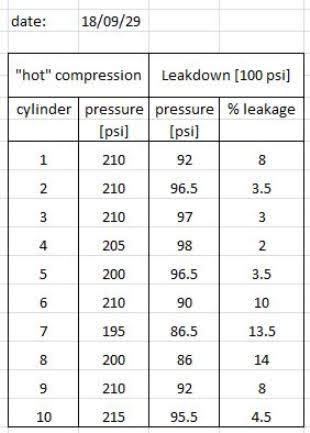
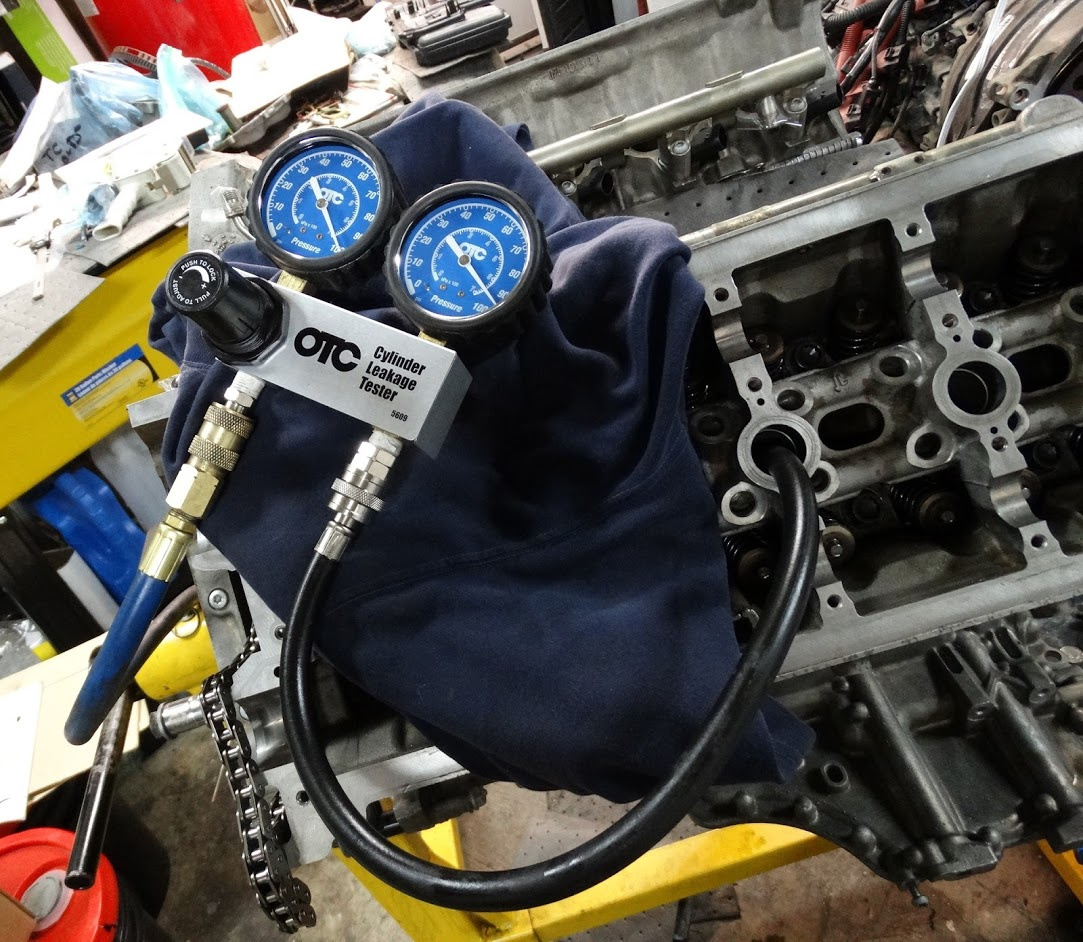
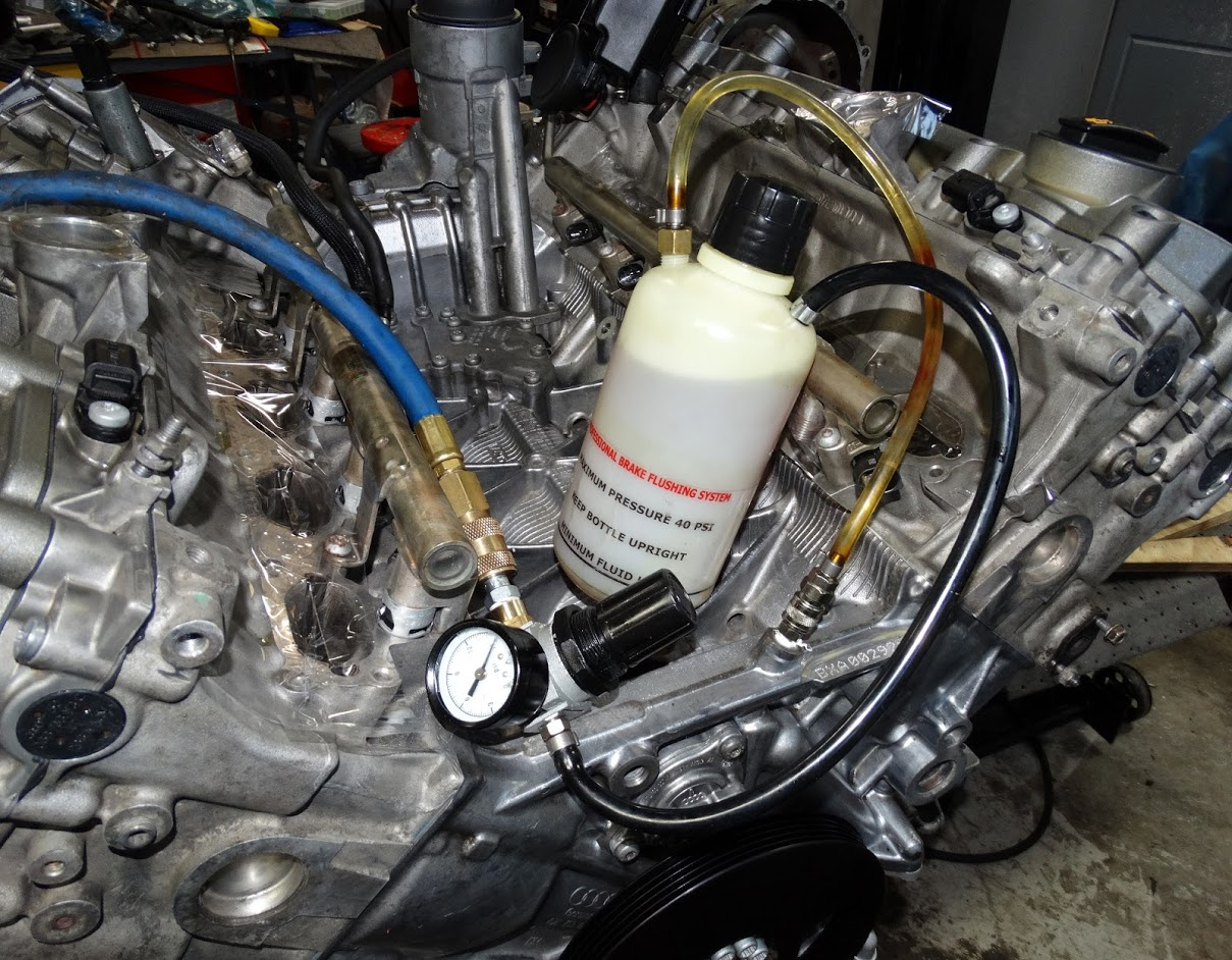
Once the oil results came back, I performed compression and leak down testing to give me an idea of the general health of the engine and if there was evidence of a head gasket failure.

Below is a summary of the numbers I obtained. The compression was quite reasonable across all cylinders. The numbers were still climbing when I stopped cranking but I wanted to limit it to six compression cycles on each cylinder for consistency. The leakdown numbers were ok with a couple of cylinders posting notably higher leakage rates than the others. At no point did I hear air coming out the intake, exhaust or adjacent cylinders so I was confident at this point that the leakage was mainly blowby past the rings into the crankcase. I will redo the leak-down test before I re-install the engine back in the car.

image

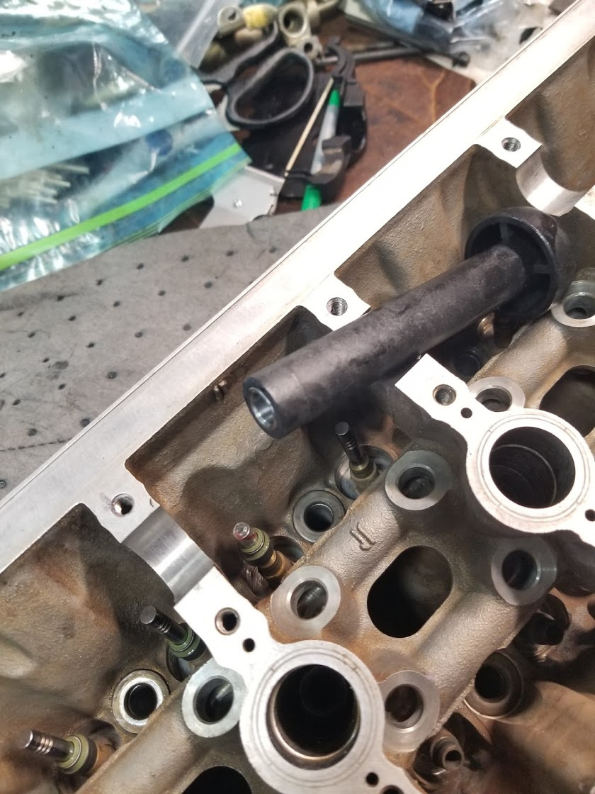
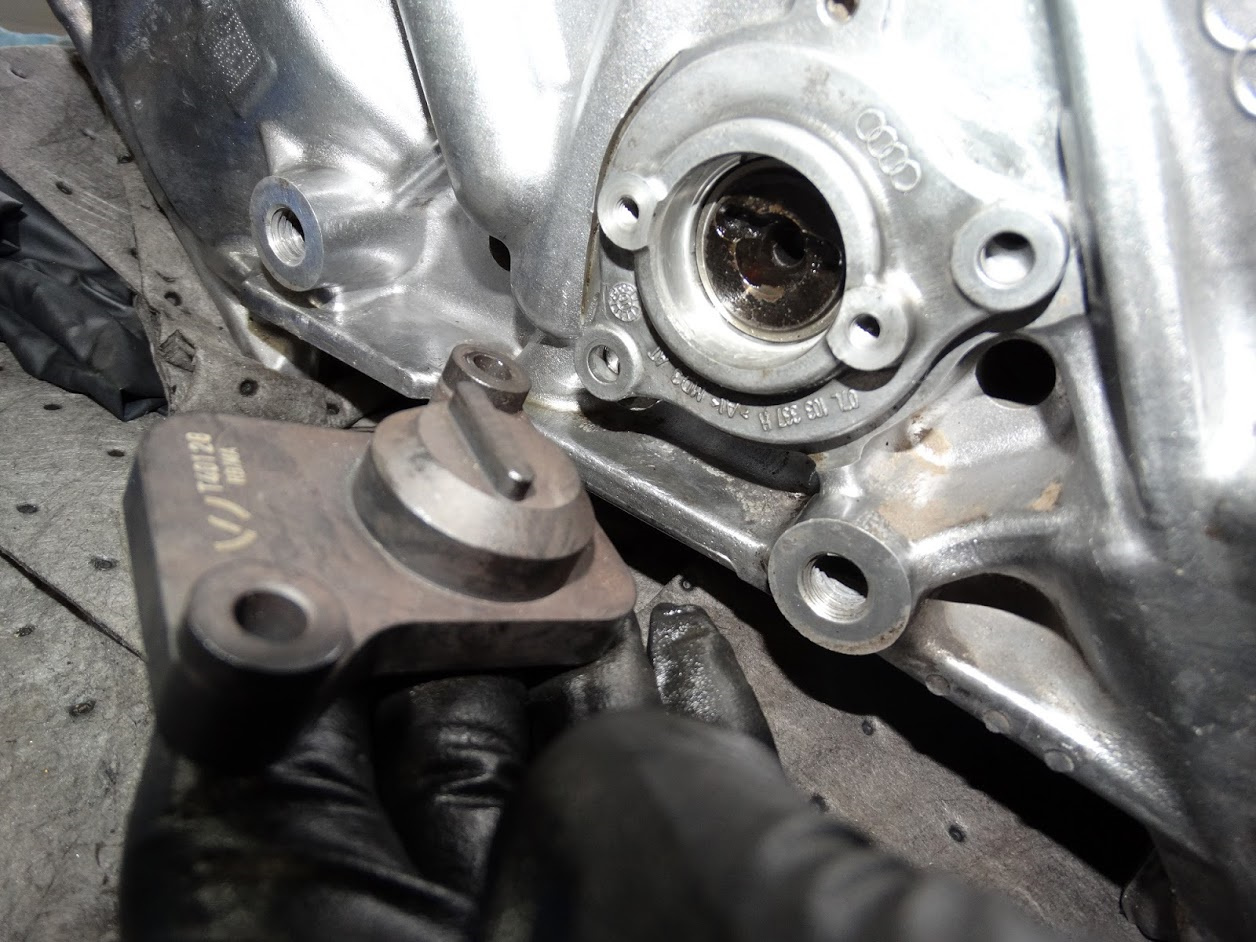
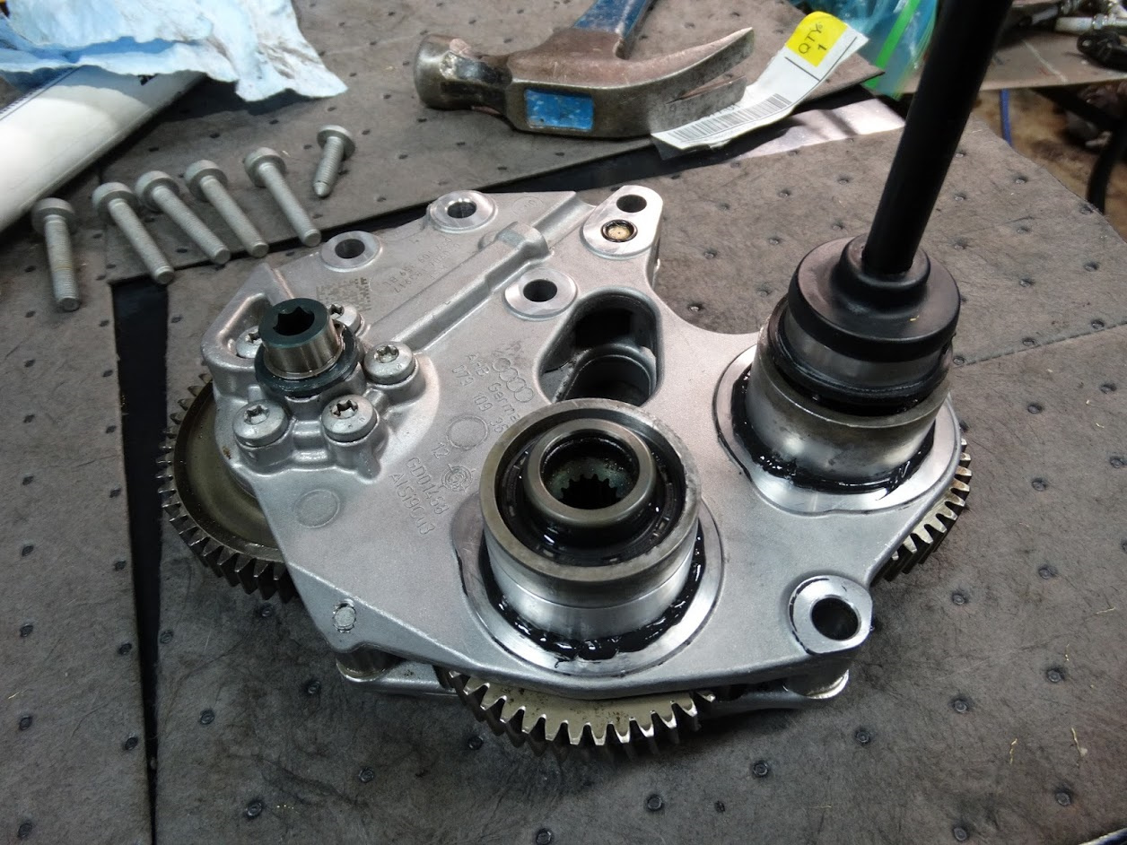
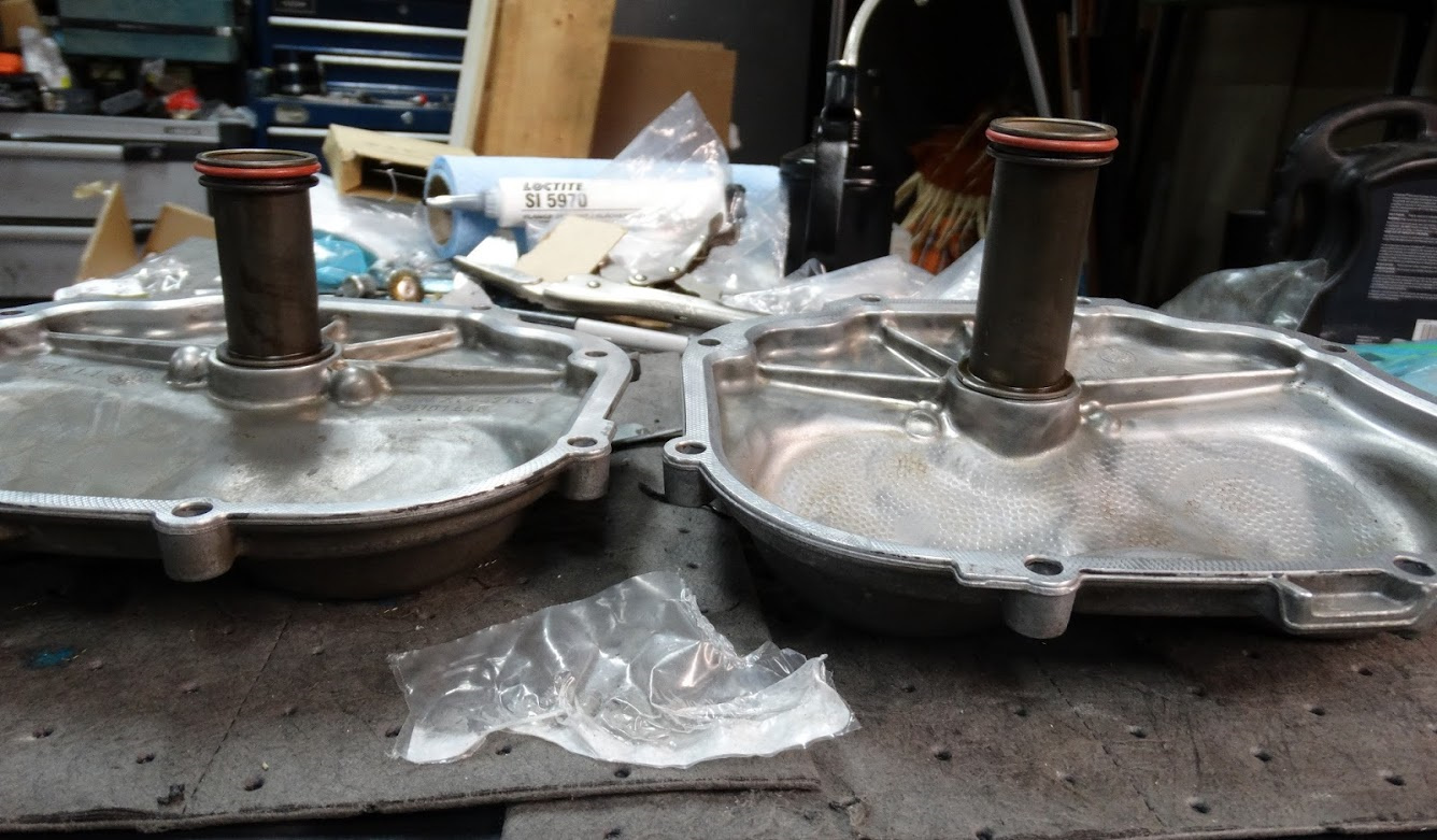
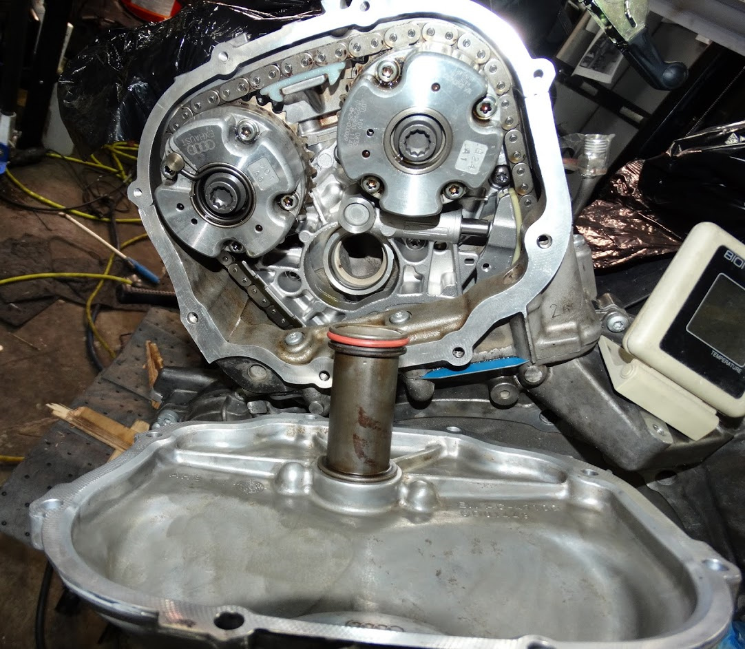
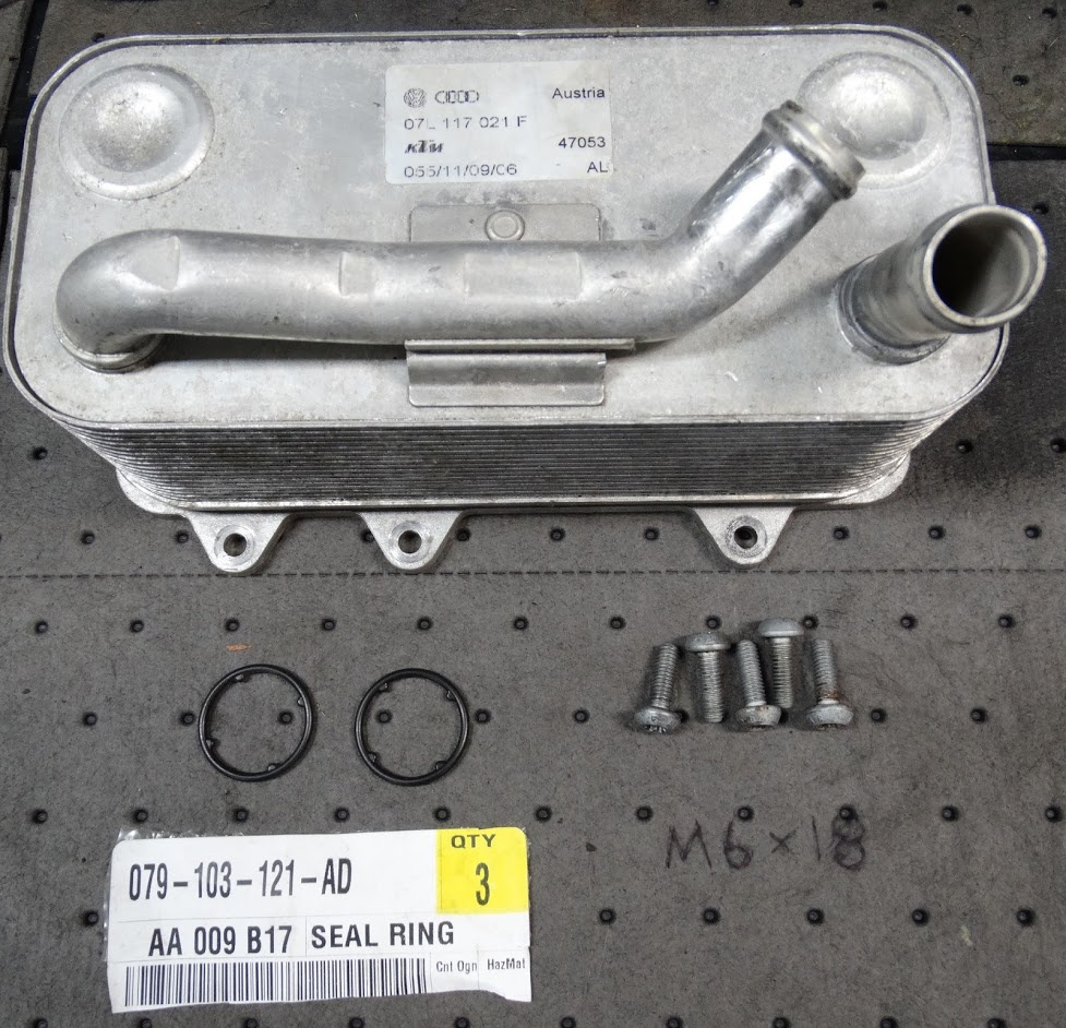
Other than the head gasket, the only other potential oil/coolant mixing points I could think of were the oil cooler and the internal coolant pipes that run from the cam timing covers into the ends of the cylinder heads.

At this point, I figured I would just pull the cam timing covers off and change the o-rings; then pull and pressure test the oil cooler and replace if necessary.

I am doing this work in a two-car residential garage. It was obvious that with all of the tool and storage cabinets already in there, I would not have enough room to do any work on the dropped engine with the car in there as well. I needed a way of rolling the dropped engine/tranny combo out from under the car and then a method of rolling the car out of the garage without the subframe attached.

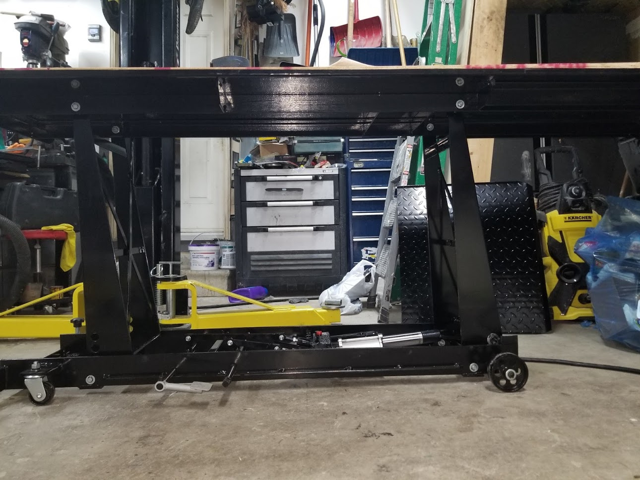
I ended up modifying a motorcycle lift by adding a sheet of plywood to stiffen up the deck and a set of four 6” casters that would contact the ground once the lift was fully lowered.

Here is a shot of the lift before the casters were added. It will make a good variable height work platform for the garage when this project is done. I would sell it but I very much doubt that this will be the last engine drop I ever do.

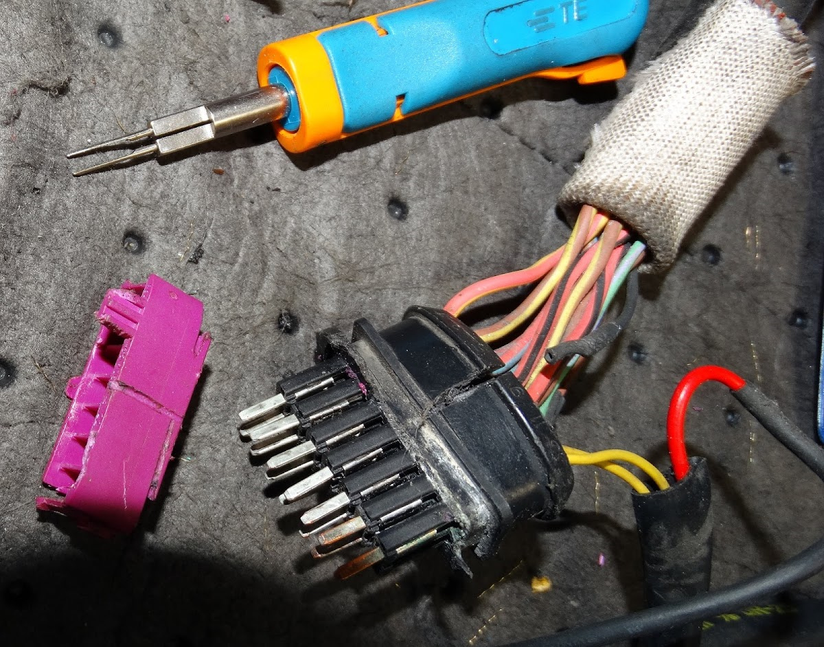
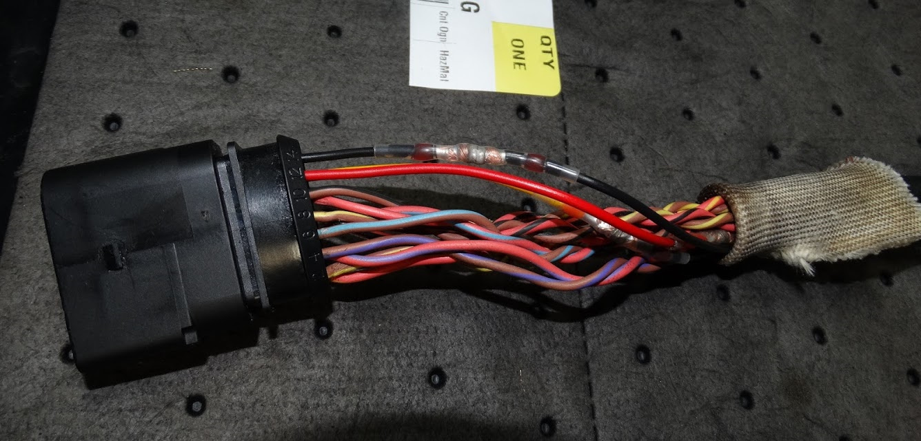
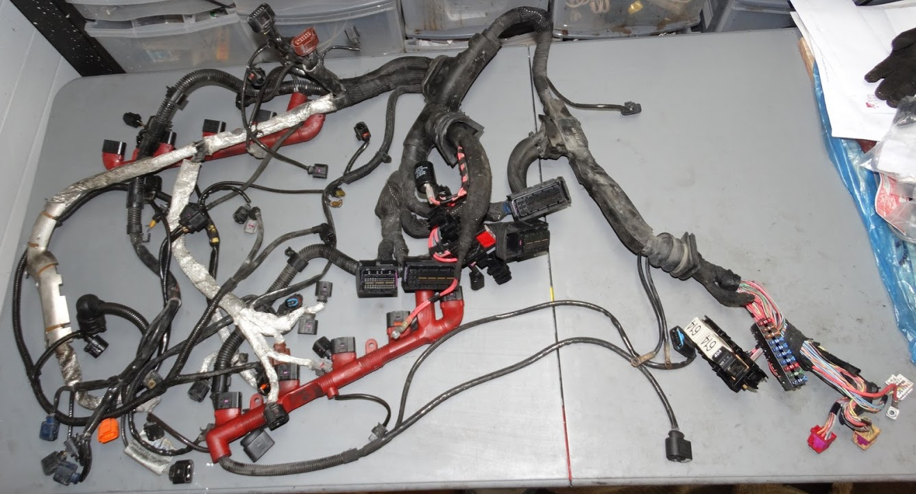
The mechanical part of the drop was very straightforward. I went pretty well by what is presented in the Bentley manual. I found removing all the electrical from under the cowling more cumbersome as you have to be very careful not to pull too hard on any of the wires as some of the connectors are getting quite fragile in their old age. When you are lowering the engine (or raising the car), the ecus and all of the other electrical has to be piled on top of the engine. In my case, I really had to watch the height as I can only lift the car so high in my garage and I still had to be able to roll the lowered drivetrain out from under it. It cleared by about 2”.

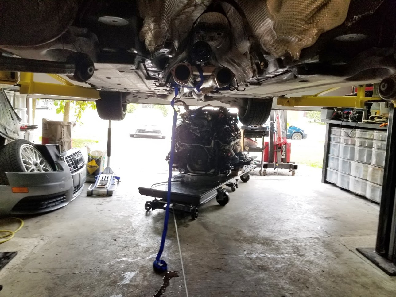
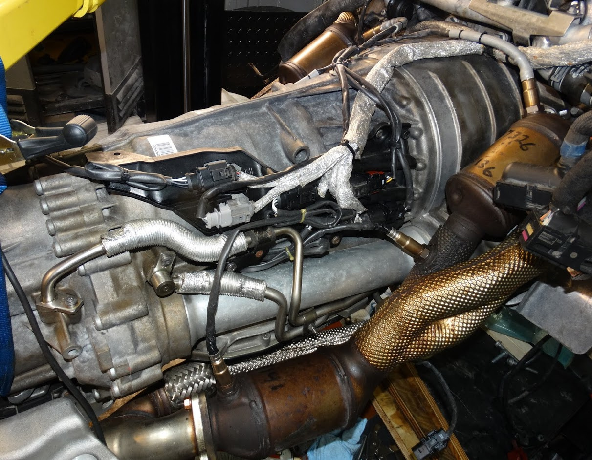
Here is a shot of the dropped engine being rolled out from under the car. You will notice that I have a winch line on it to keep it from getting away on me due to the slope in the floor of my garage.

To get the car out of the garage, I lowered the front end onto a dolly I made and pushed it out using a winch to stop it from getting away on me due to the slope of the driveway. I will also need it to pull the vehicle back in for the re-install.

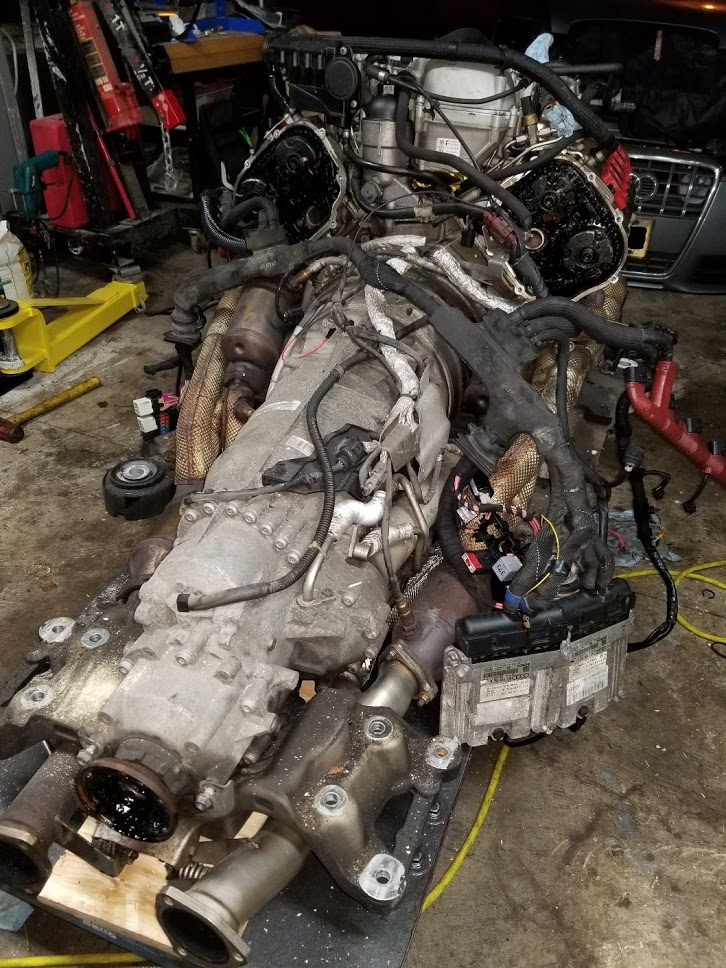
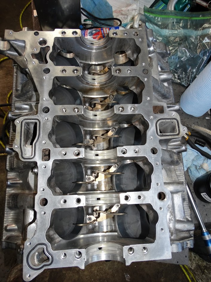
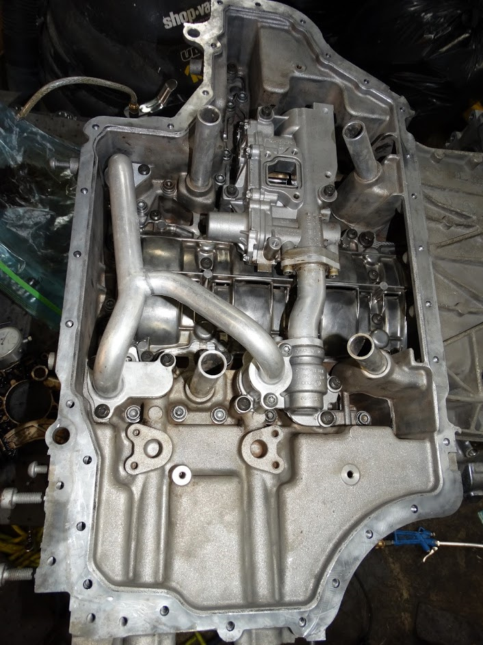
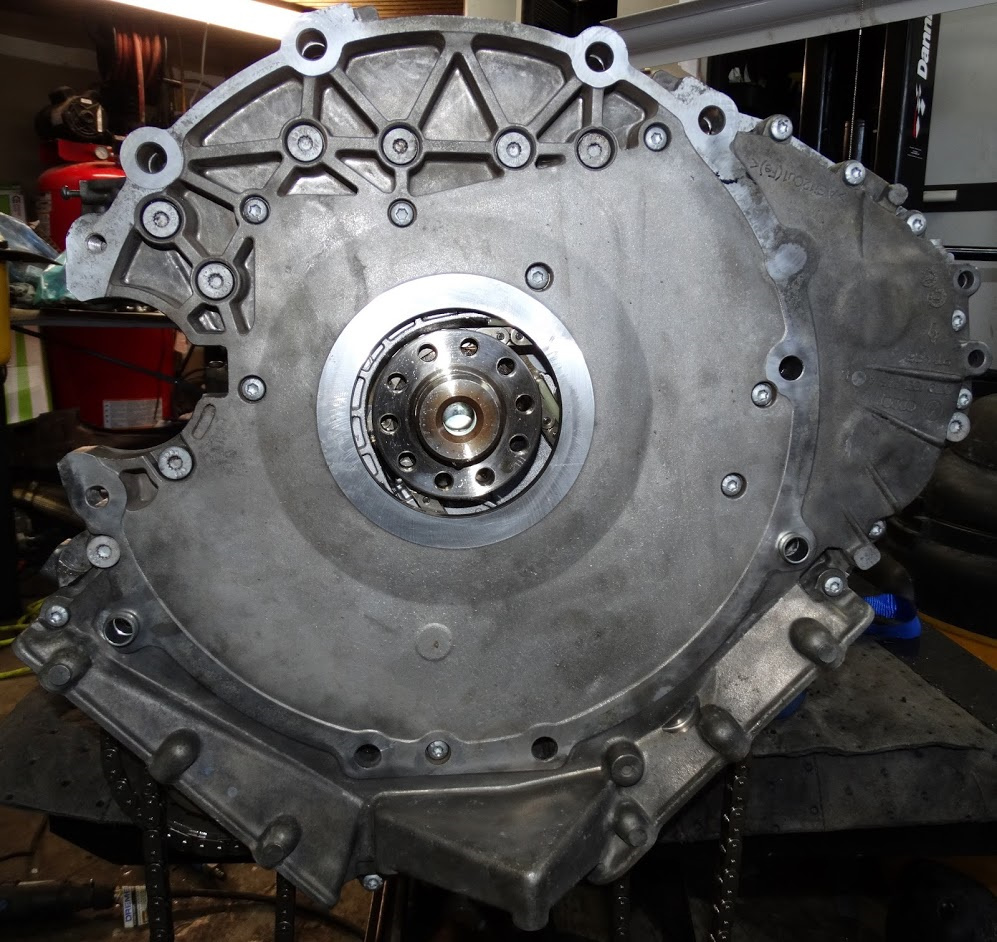
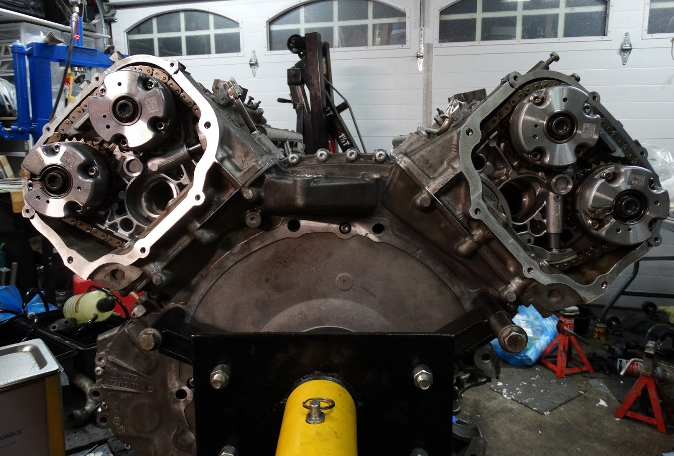
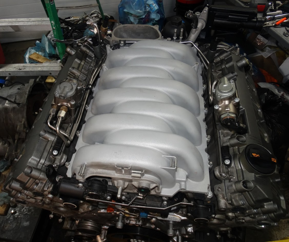
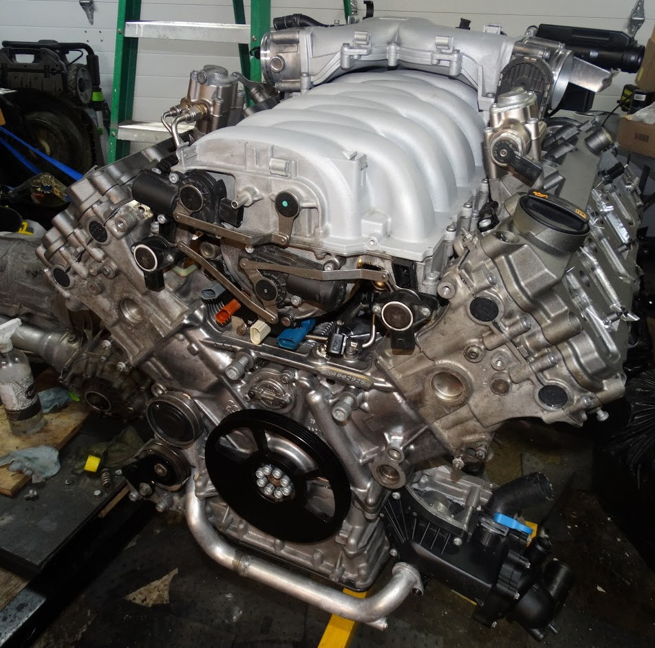
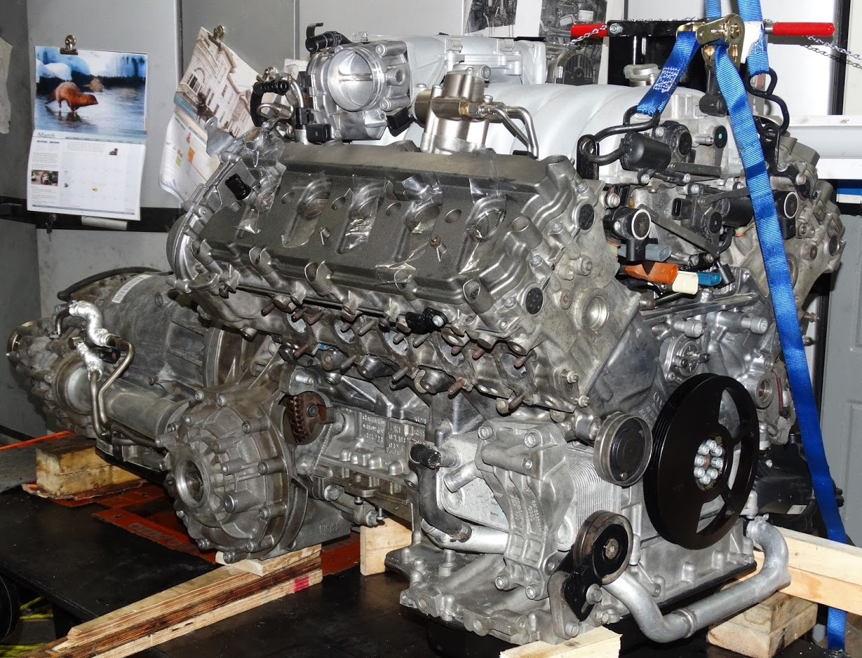
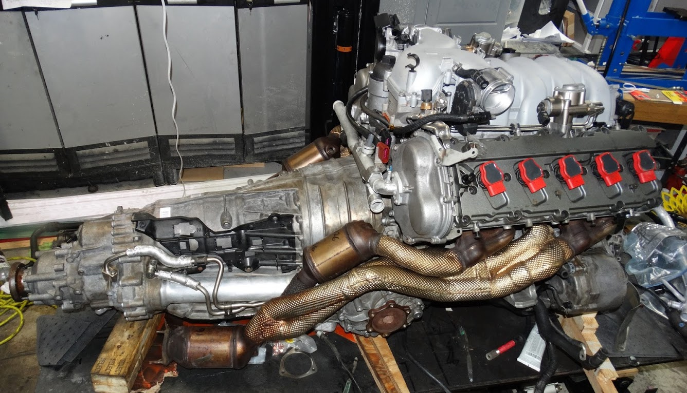
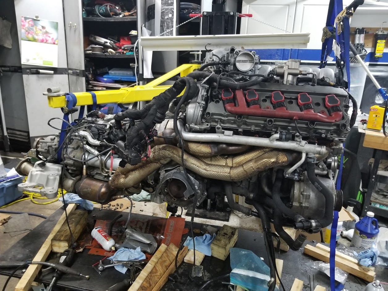
Here is a shot of the dropped powertrain on the lift. You can see the front end of the car on the dolly in the background.

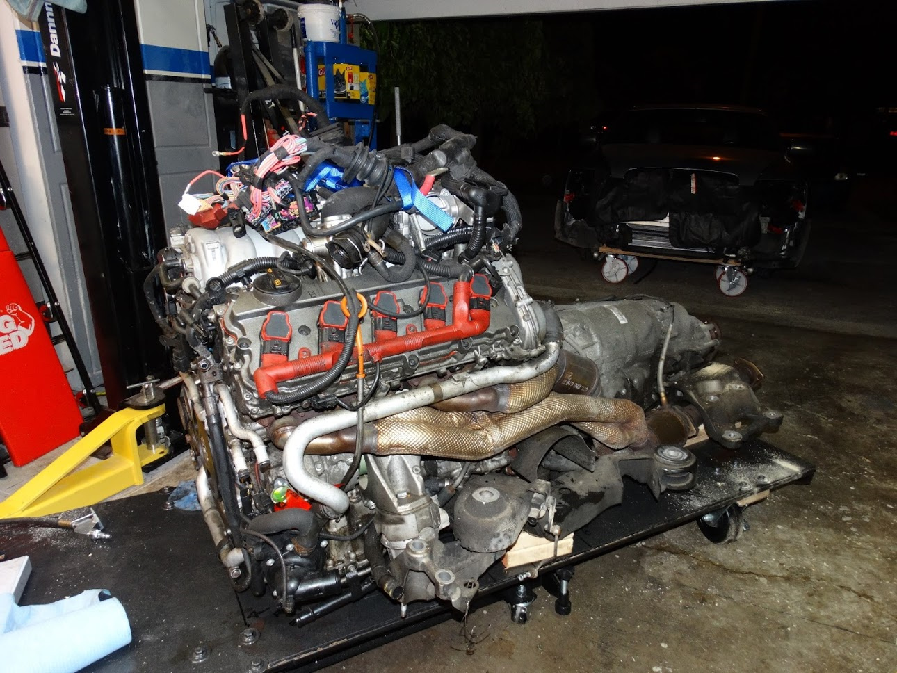
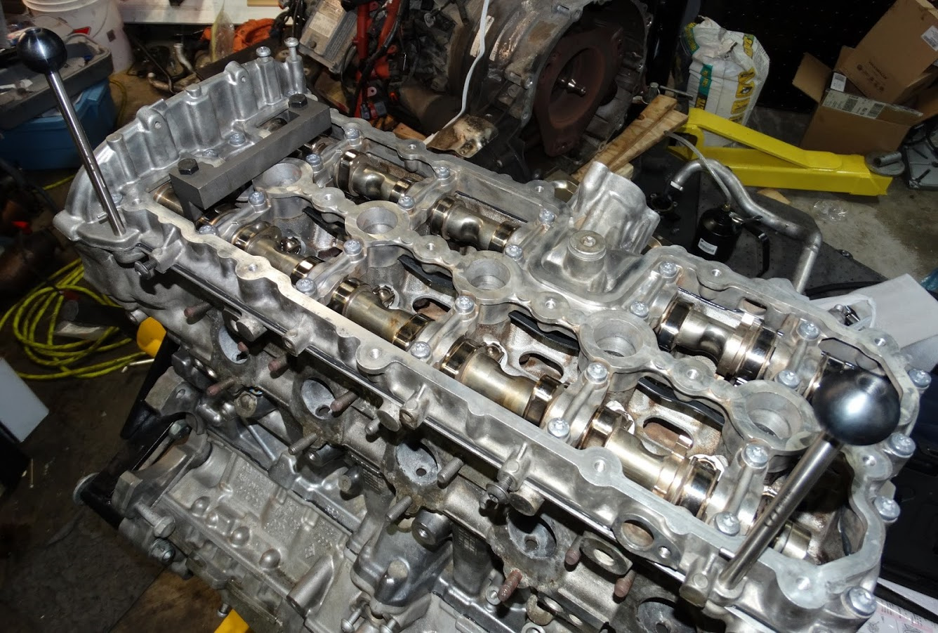
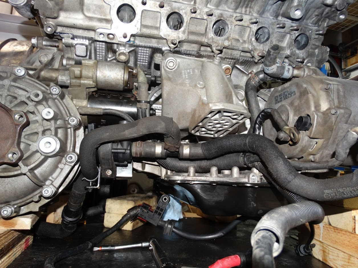
Another one taken from the rear. One of the many pics that I took during the disassembly process.

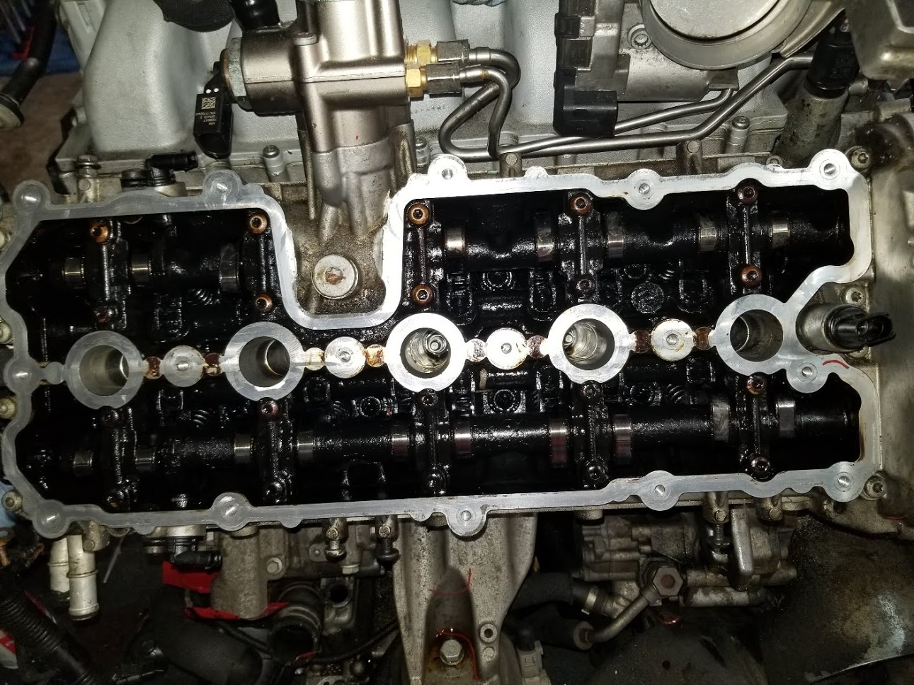
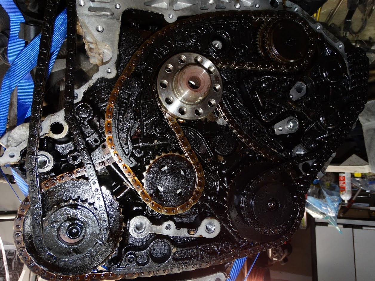
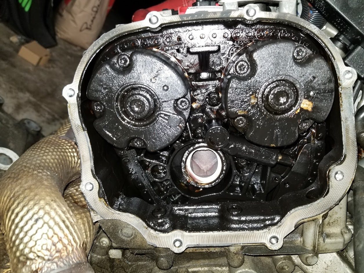
You will note that the rear cam covers have been removed and it is not real pretty inside

Here is a closeup:

This stuff is like tar. It does not come off easily with a simple wipe of a rag.

I am pretty sure this is the result of a major overheating (due to loss of coolant) incident that I had a couple of years ago. The engine got so hot that the red oil light actually came on. I had already been driving for about a half hour with the engine coolant temperature gauge pinned but it was a situation where I could not stop the car so I drove for another couple of minutes (with the oil light on) till I got to my destination and then shut it off. I thought for sure the engine was done. It was not a good situation as I was 200 miles from home in an underground parking garage with no tools. I went out the next morning to see if I could find the source of the coolant leak. I could not see anything given the limited visibility we have of the hoses under the hood. The oil level on the dipstick was good although it was a little on the dark side. I had to get the car out of the underground parking so it could be loaded onto a flatbed for the long drive home. I was quite relieved when only the coolant level warning came on and not the one for the oil when I started the engine. After getting it home, I found that the short right-angled coolant hose that connects to the alternator had failed. Its premature failure was likely the result of me being a little too rough with it when I changed out my oil cooler o-rings about 4 weeks earlier

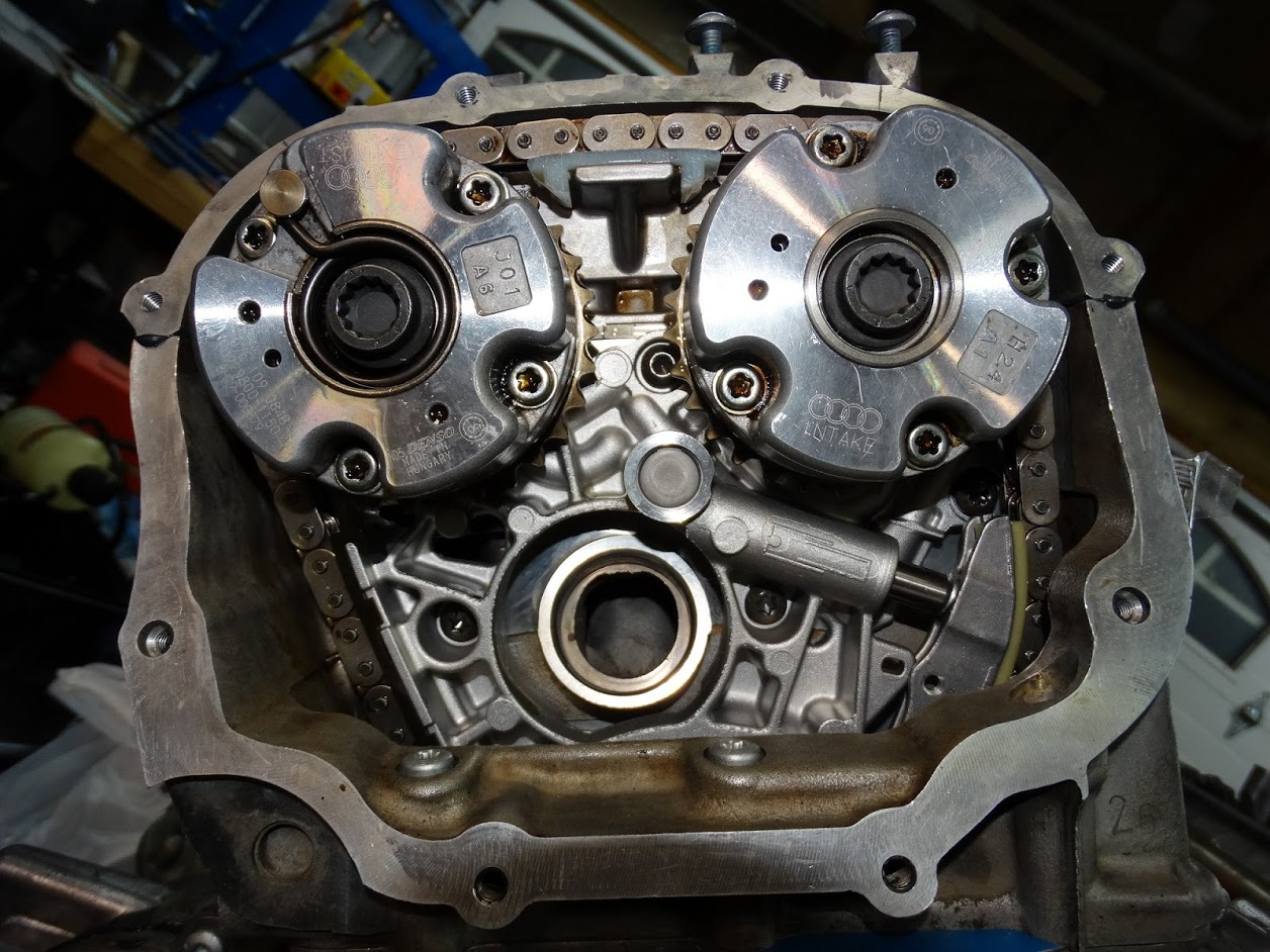
Here are a couple more pics showing the extent of the overheated oil situation

Under valve covers:

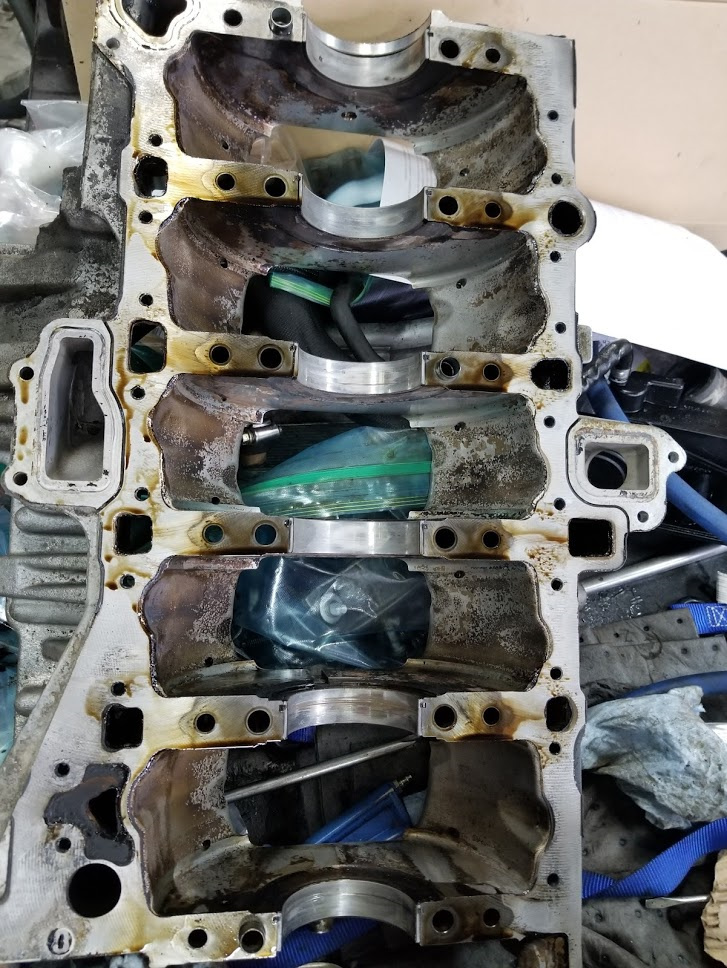
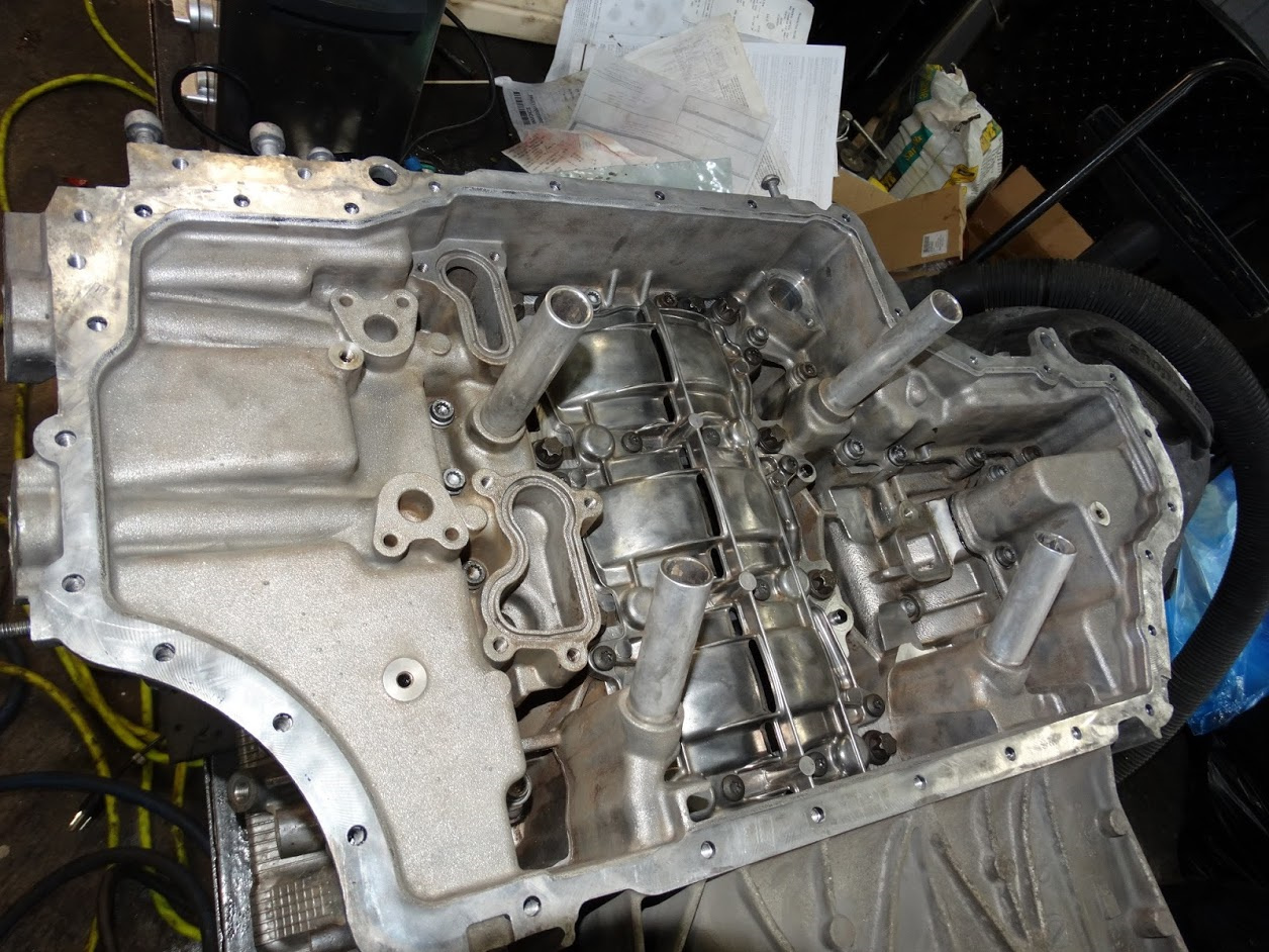
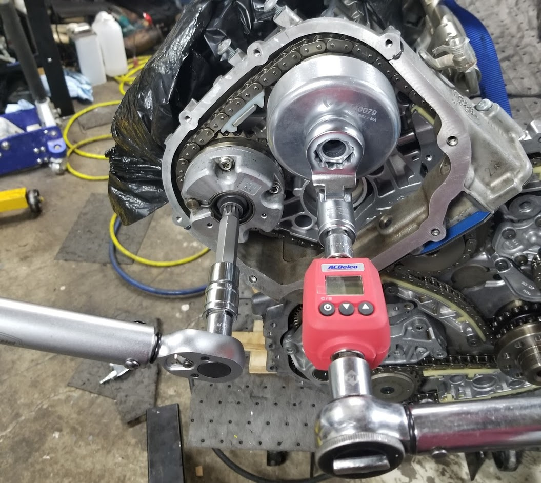
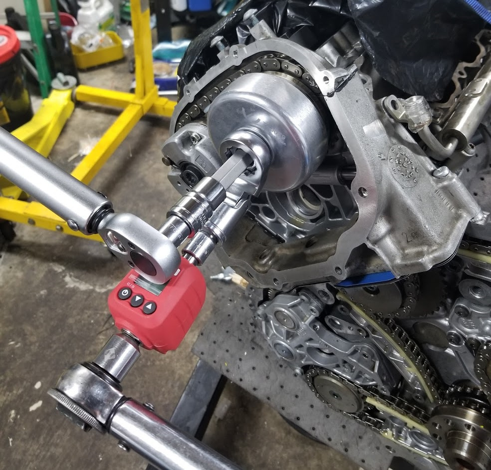
Oil pickup tube and pump inside upper oil pan:

After seeing all the “cooked” oil, I decided I was going to have to take it right down to the bare block to inspect and clean everything.

At this point, I am going to fast forward to the stage I am at right now as I am sure pictures of dirty parts in a partially disassembled engine are not going to be of interest to a lot of you.

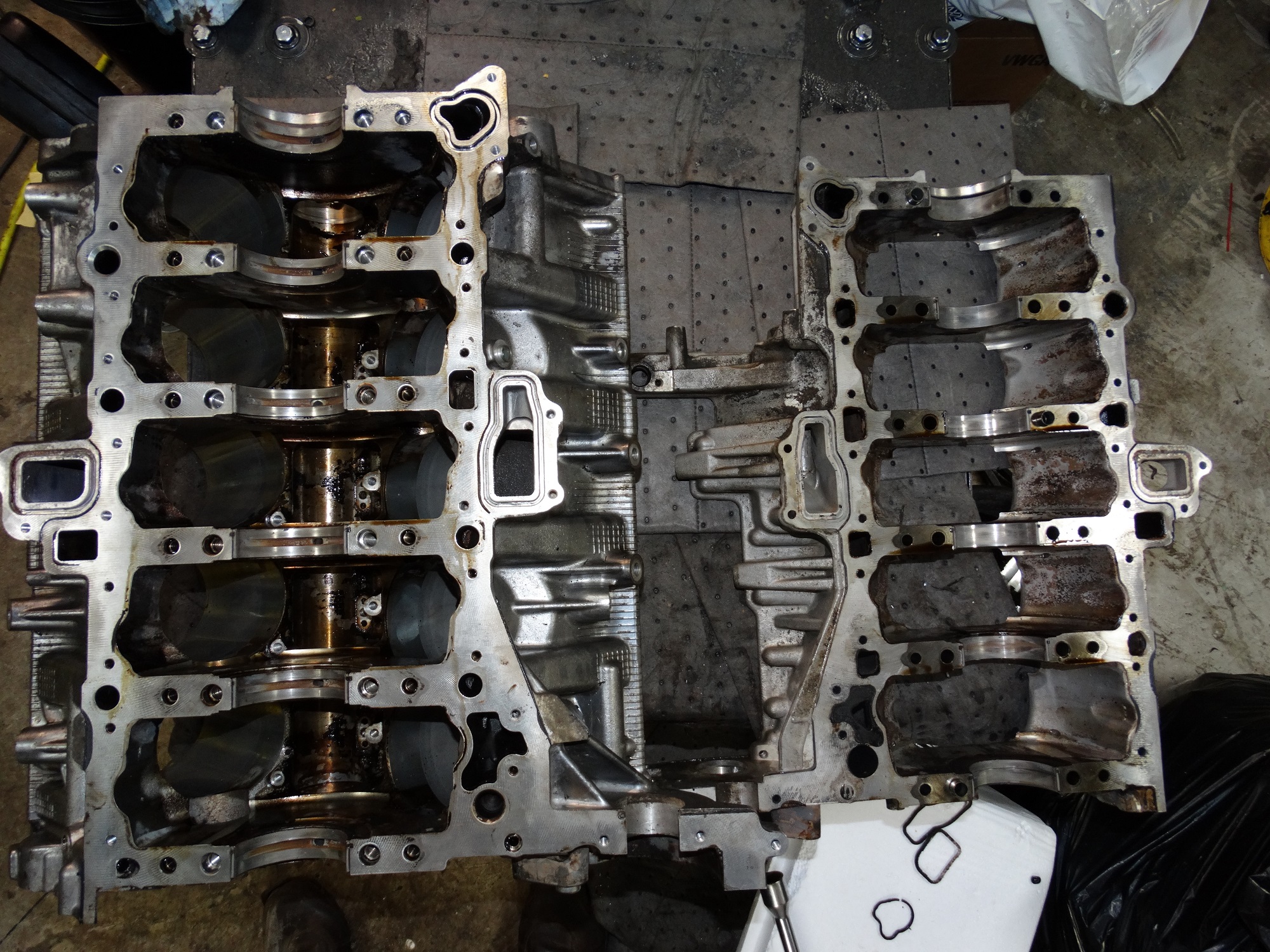
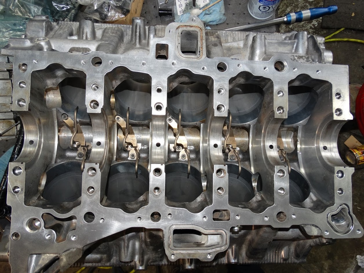
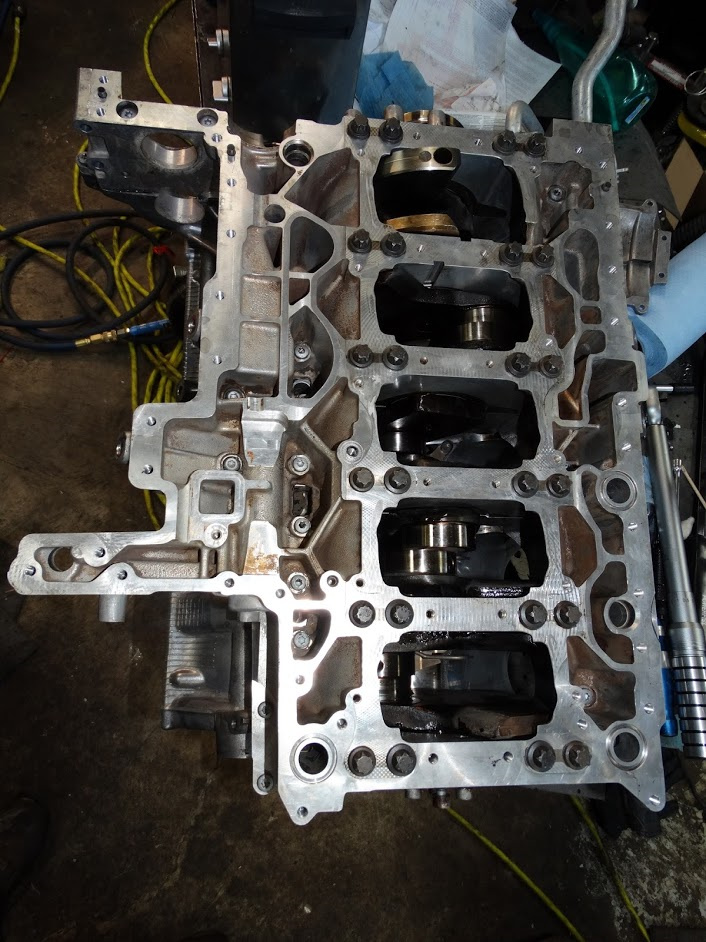
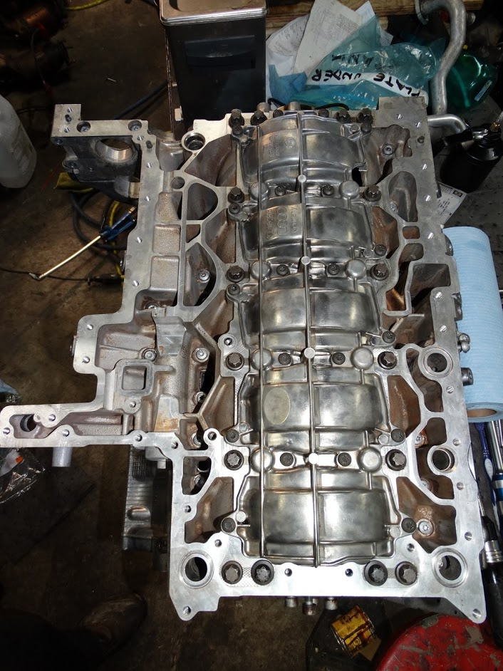
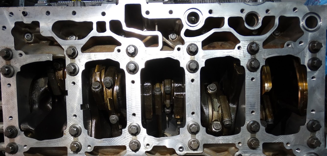
I have the cylinder block separated from the crank guide plate with the crank removed right now.

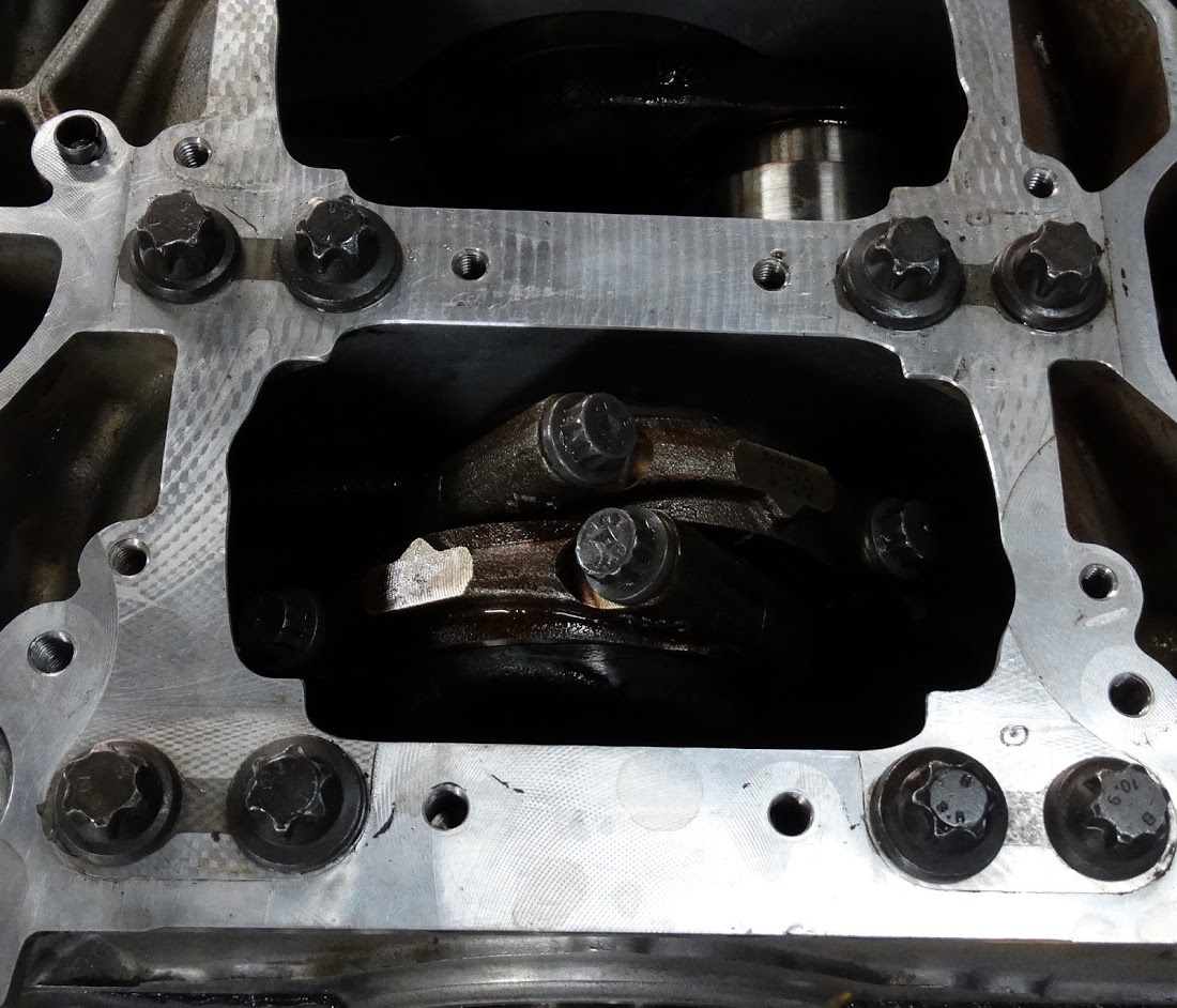
I wanted to see the condition of the connecting rod and crank journals and bearings given the low oil pressure light that came on when I overheated the engine.

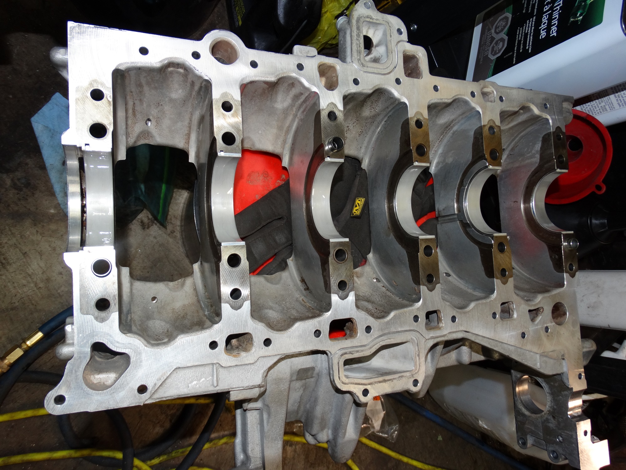
Here is a shot of the crank guide frame (engine bed plate) with the lower bearing shells still installed

As you can see, there is a fair amount of scoring in the bearing for journal number five and some to a lesser extent in the other five bearings. The crankshaft journals all look fine.

I did not take any pictures of the rod bearings. There was no scoring on them; just scuffing similar to what you see on the bearing for journal #1 above.

I have replacement upper and lower bearing shells for both the crank and rods on order along with all of the bolts. I will be verifying that the radial clearance for all of the bearings is within spec before torquing everything down.

That is it for the disassembly.


Phase 2 - Cleaning

Definitely the most tedious part of the process. This is one of the few instances where you would rather have a four banger.

I started with a number of different solvents including simple green, varsol, combustion chamber cleaner, brake cleaner and lacquer thinner. I wear gloves and an organic vapor mask when working with any of them.

The run-off is contained using PIG absorbent mats which are then dropped off at the local hazardous waste depot once saturated.

The brake cleaner is nice because it is a relatively strong solvent and the pressure from the spray helps to dislodge the larger chunks of buildup. I have gone through about fifteen cans so far cleaning the block, heads and the other large components.

Tooth brushes and other assorted scrubbers are used to remove the build-up that has been softened by the solvents. I do not use any metallic brushes (including brass) because they scratch the aluminum parts.

The lacquer thinner is probably the strongest solvent of the ones I use. It breaks down my 8mil nitrile gloves and I have to change them every half hour or so.

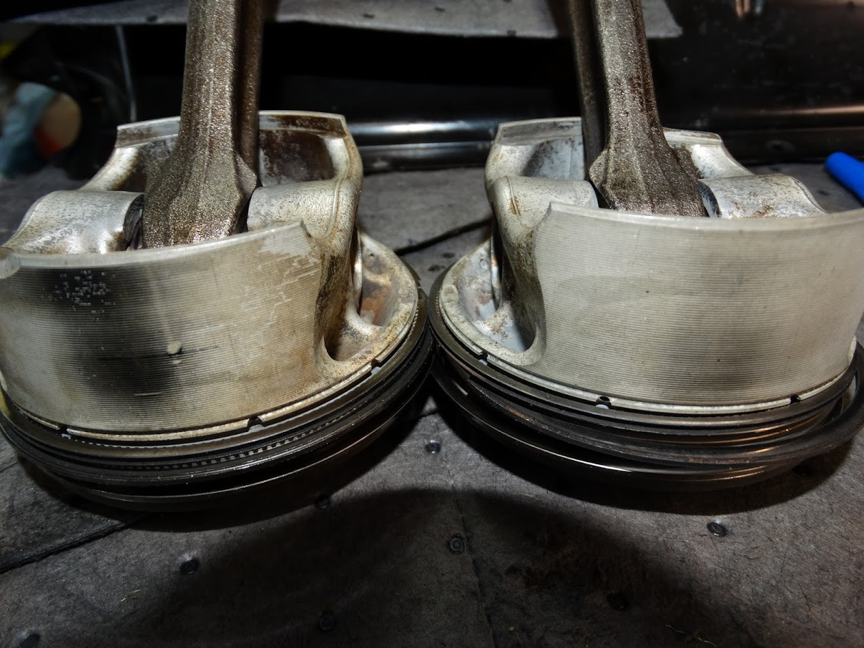
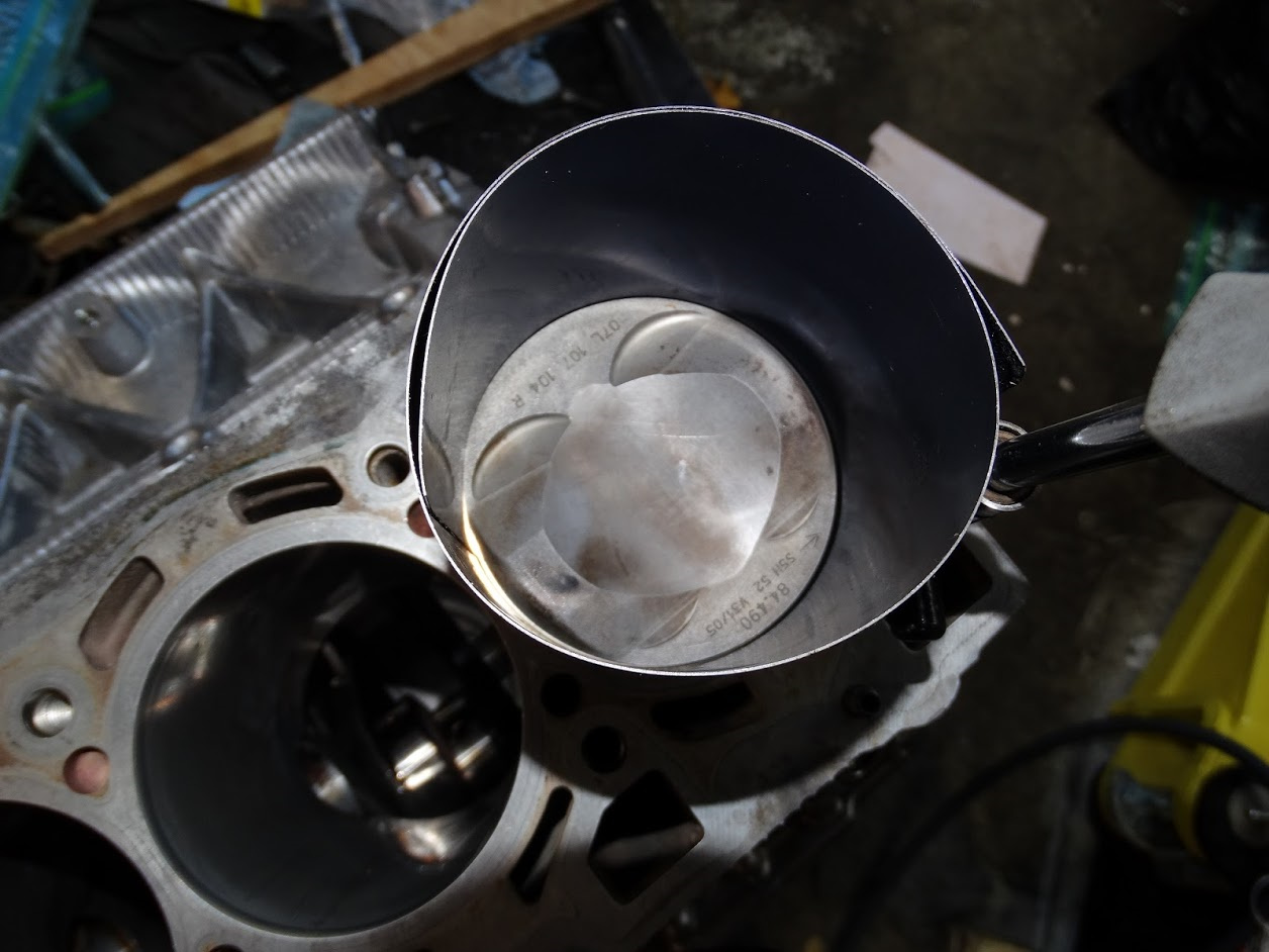
I was using it in a small glass container to clean the piston crowns and the ring grooves. The oil scraper rings have very small holes in them which were all plugged with burnt oil. Even after soaking them in lacquer thinner, it was a very laborious process to clean them with a tooth brush.

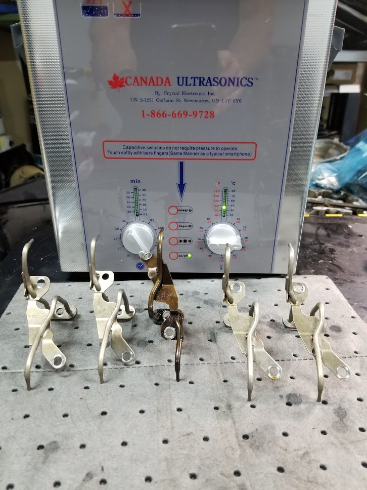
It was at this point that I decided to acquire an ultrasonic cleaner. After using it for a few days, I wonder why I did not invest in one years ago for cleaning parts. It probably is not any faster to clean things with, but it does a much more thorough job and there is no toxic odor in the air.

You do have to be careful with the heat setting and aluminum parts though as it will tend to darken them.

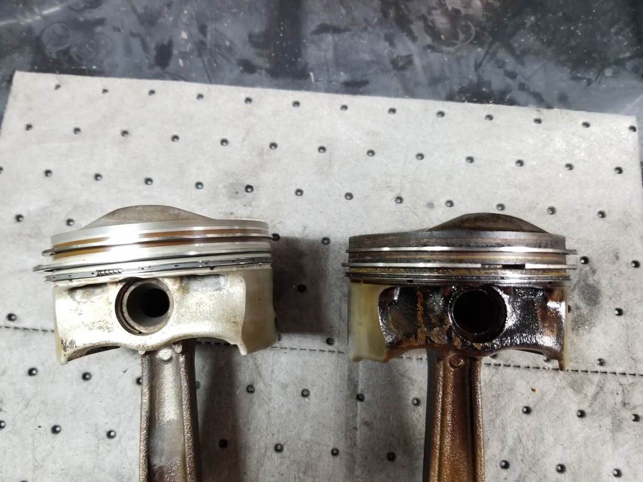
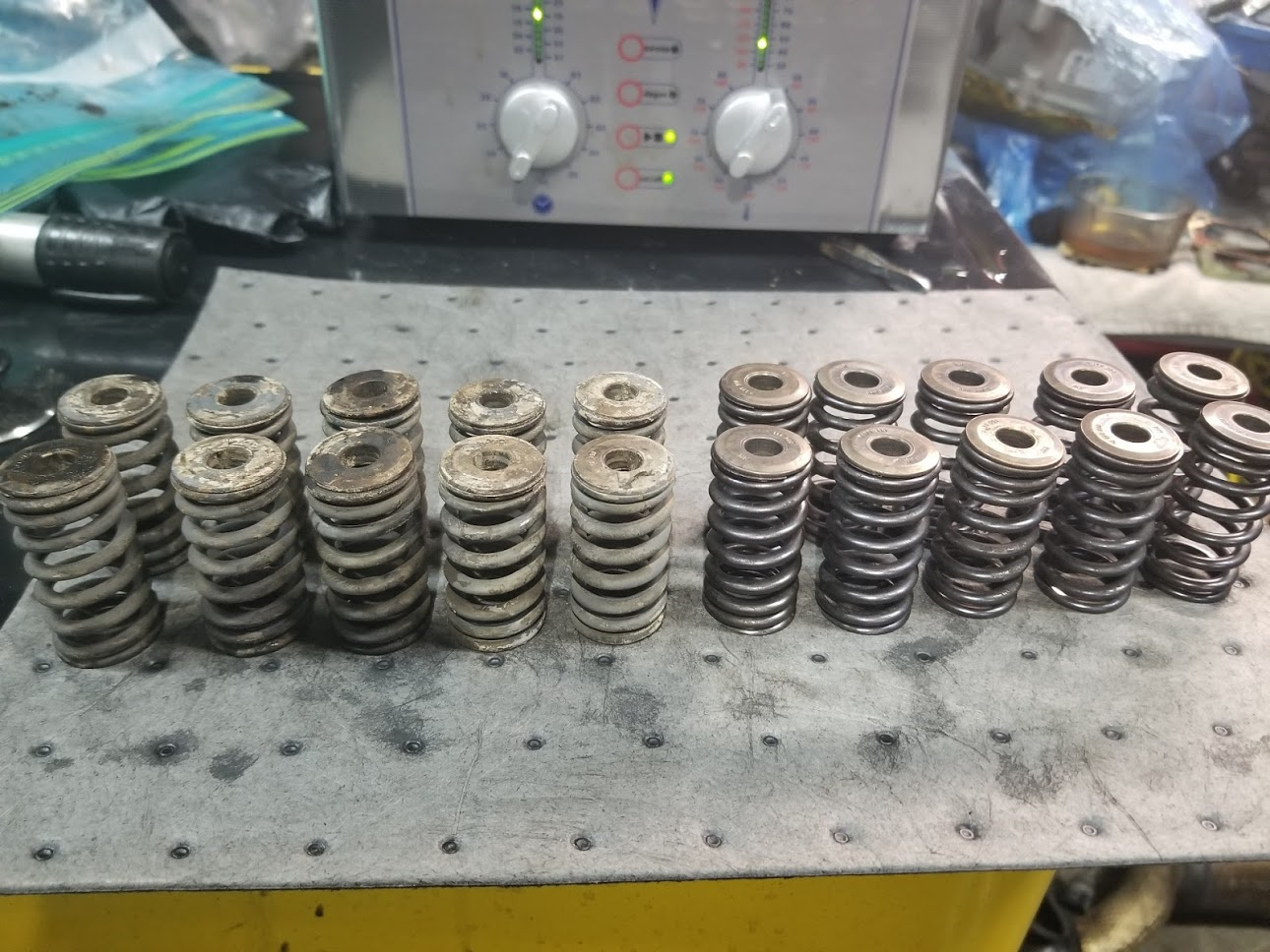
Here a few examples of before and after results
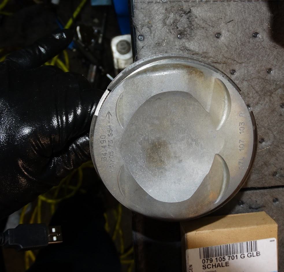
oil squirters

pistons

cam chains

valve springs

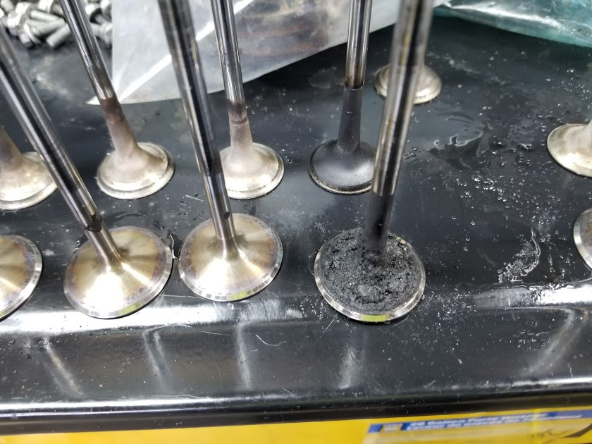
Here is a shot of a carboned up valve and one that has been in the US cleaner for about 40min. The valves are steel so I turned up the temperature on the cleaner otherwise there is no way the carbon would have come off. I still had to do some scraping with a plastic scraper to get some of the more stubborn deposits off. I will be lapping them all to the valve seats once I finish cleaning the heads.

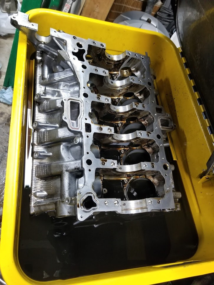
Here is a good shot of the cleaned bed plate. You can clearly see the cast iron bearing housings that are cast right into the aluminum. Until I cleaned it, you really could not tell there were two different metals there. I was wondering why the damn thing was so heavy when I lifted it off the block.

This is the stage I am at right now. The block does not quite fit in the tank but at least it will contain all the solvent run-off. It is going to take a while to do this one as there are so many internal oil passages that I have to make sure are clear.

I hope to be done with the cleaning towards the end of this week. The next step will be checking the decks and heads for flatness and making sure the crank bearing radial clearances are within spec.

I will also post up a picture and a list of all the parts that were procured for this project in the next few days.

There was not much progress this week.

The rotating postal strikes up here have delayed the arrival of some of the things I need to move forward by a few days.

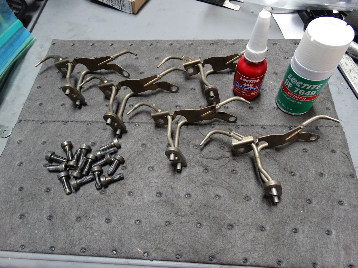
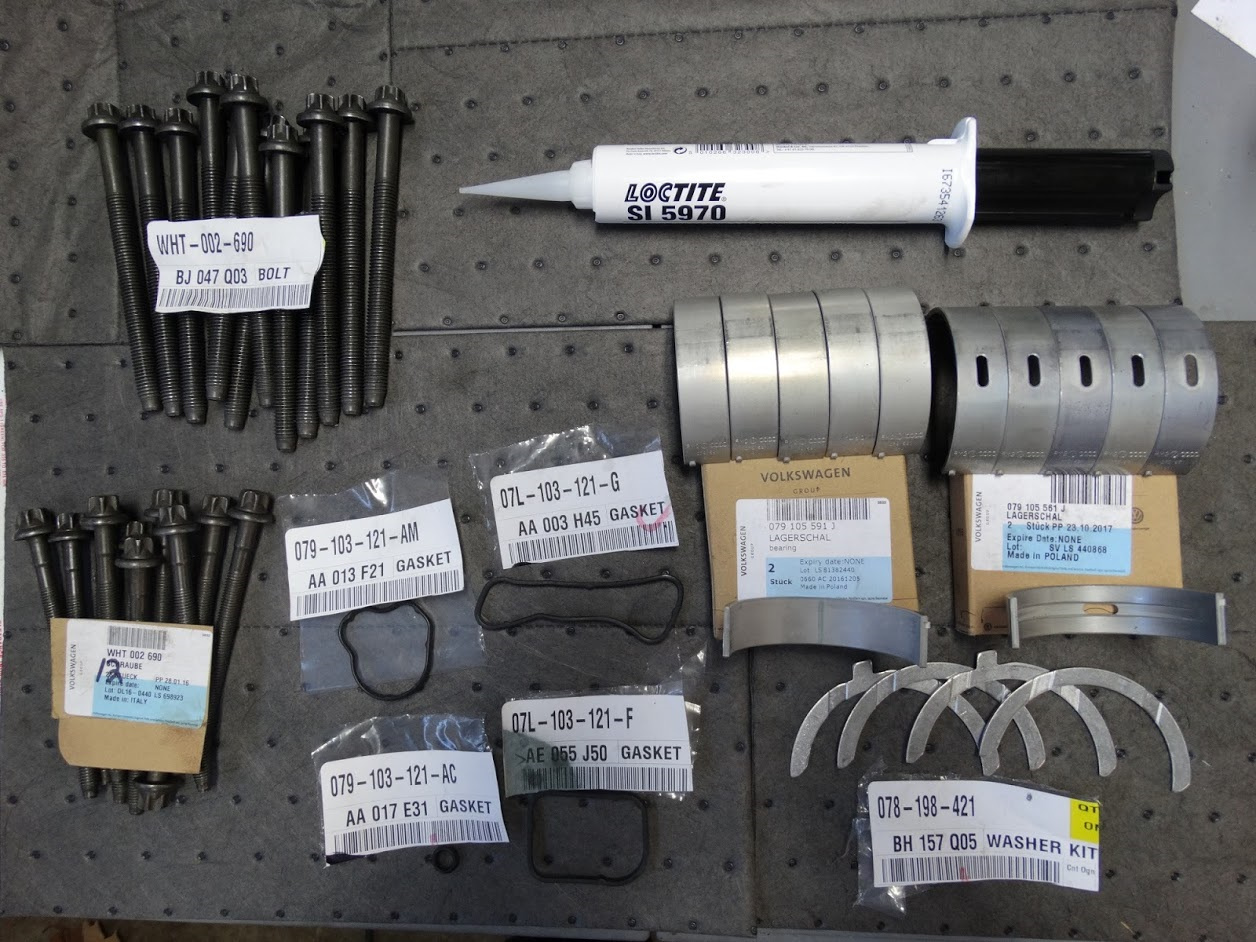
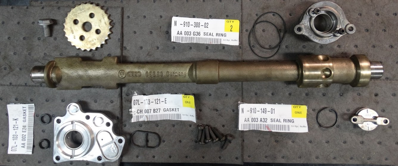
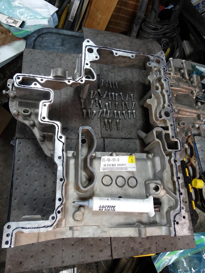
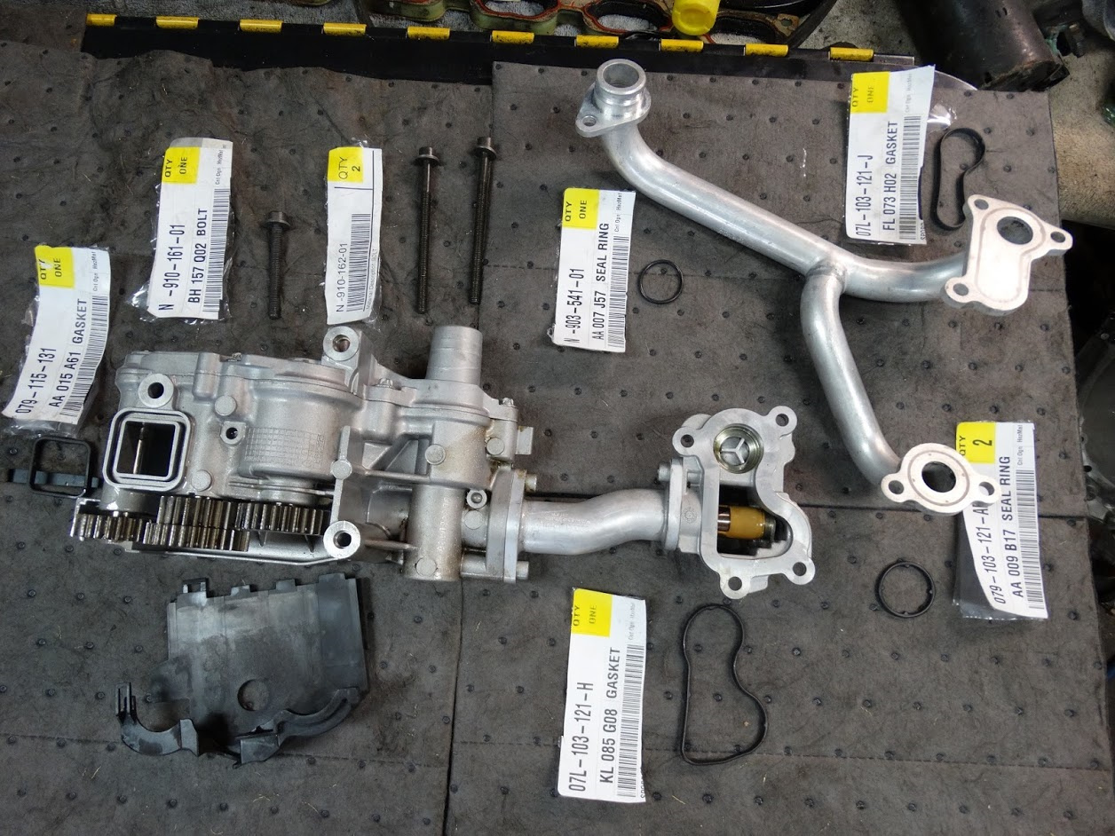
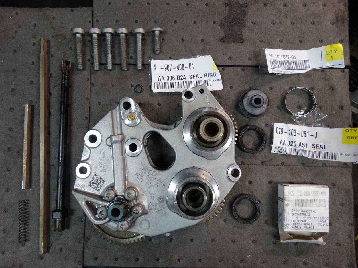
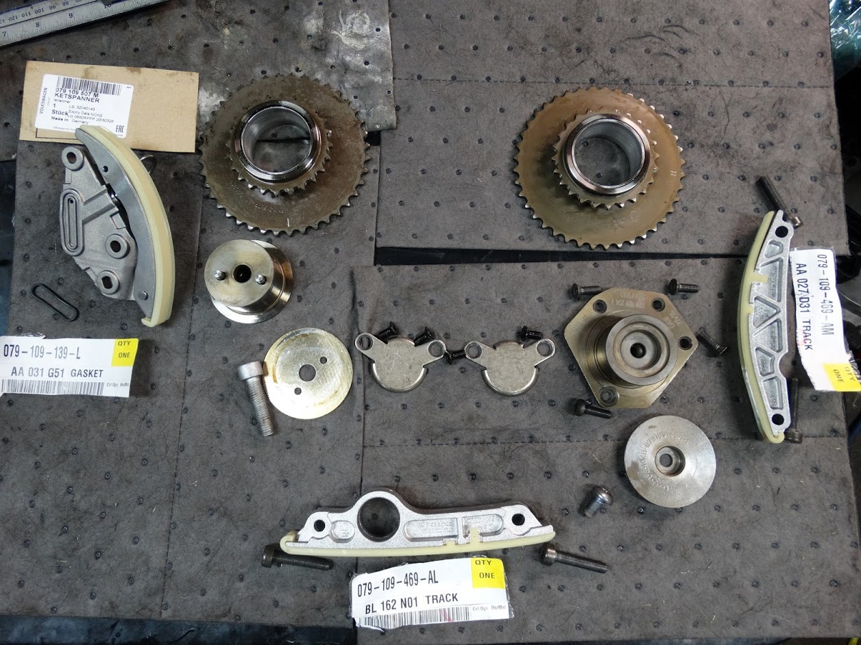
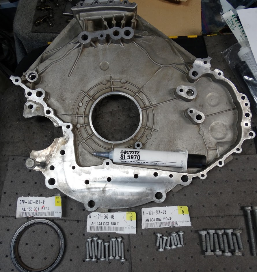
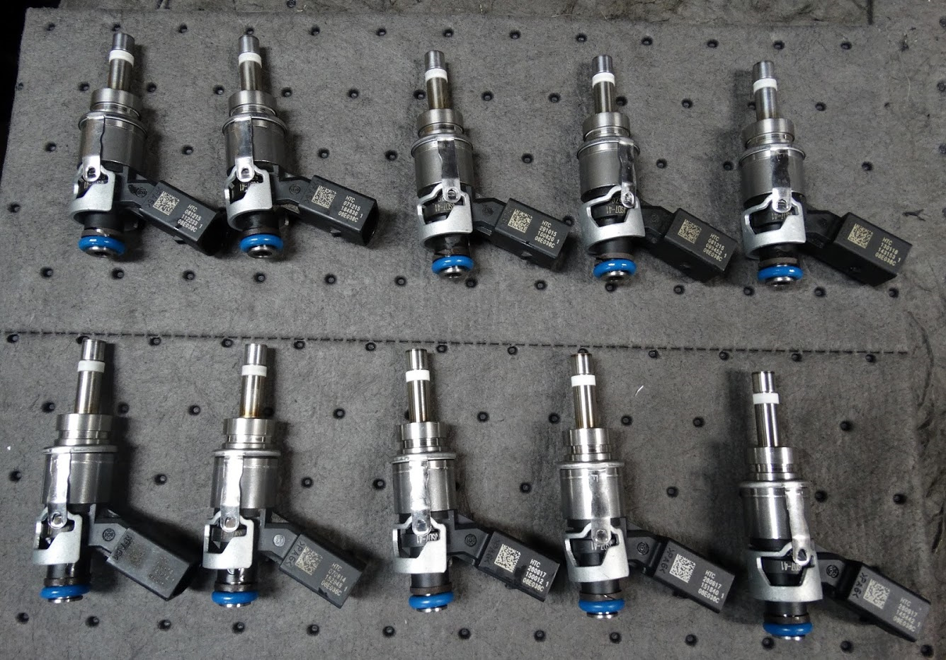
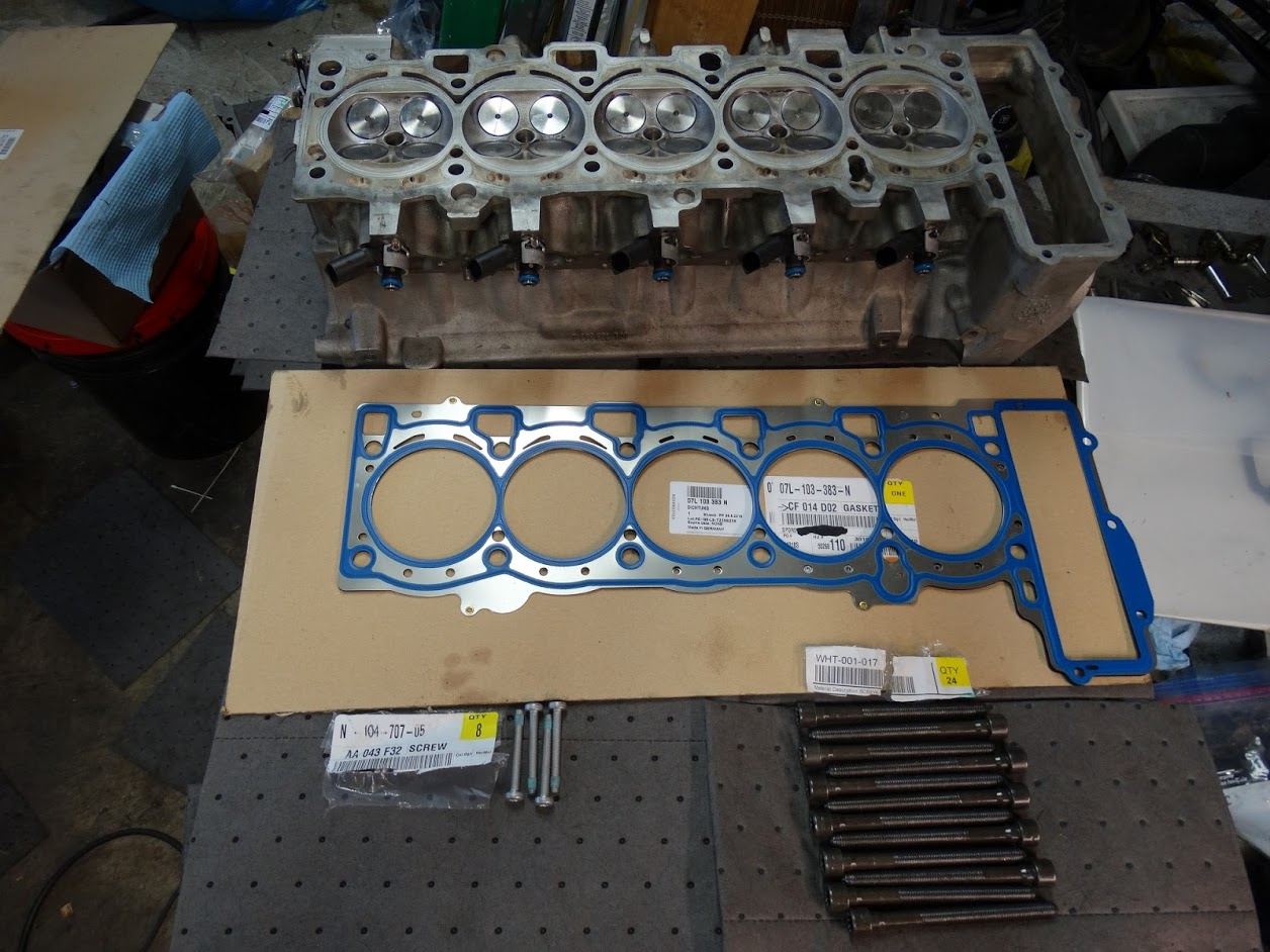
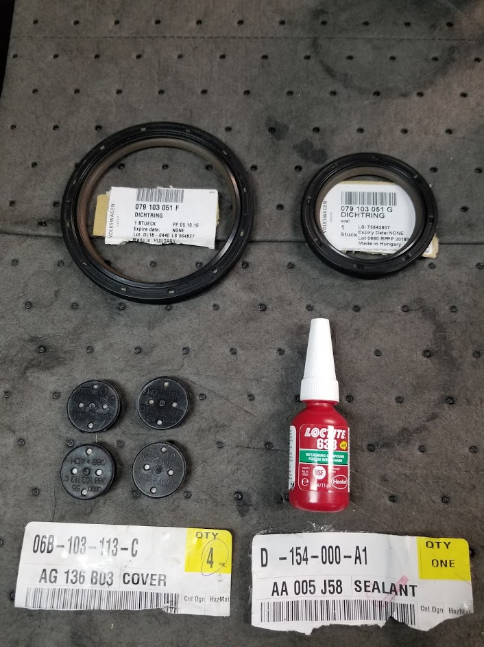
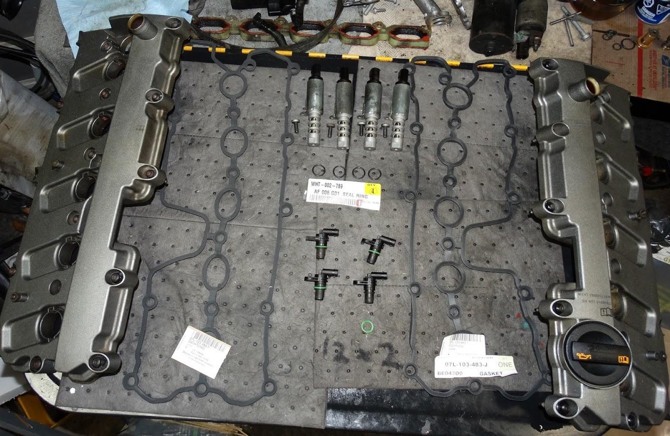
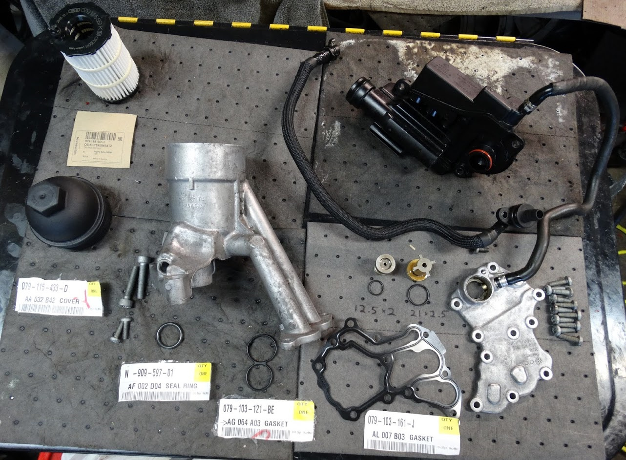
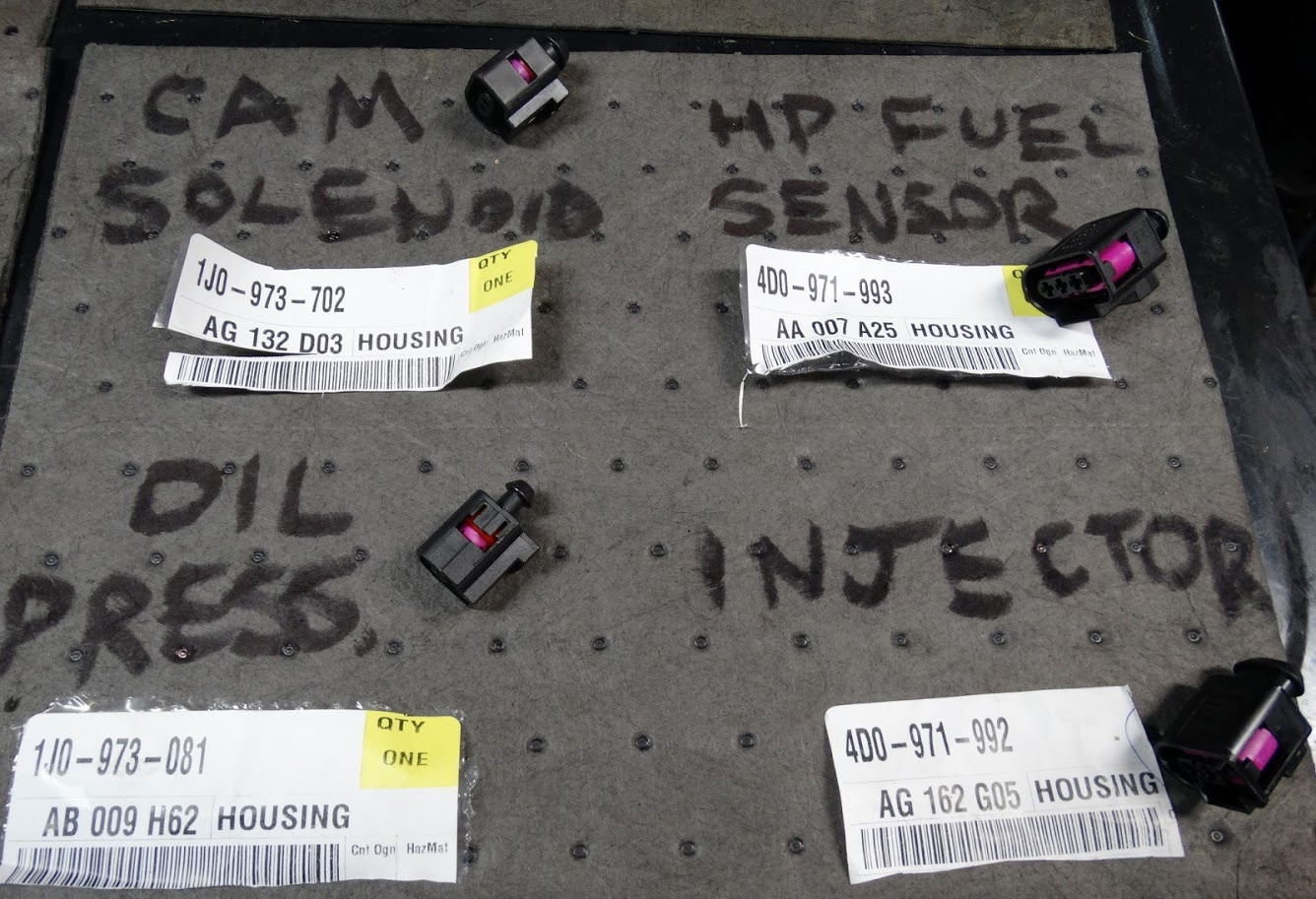
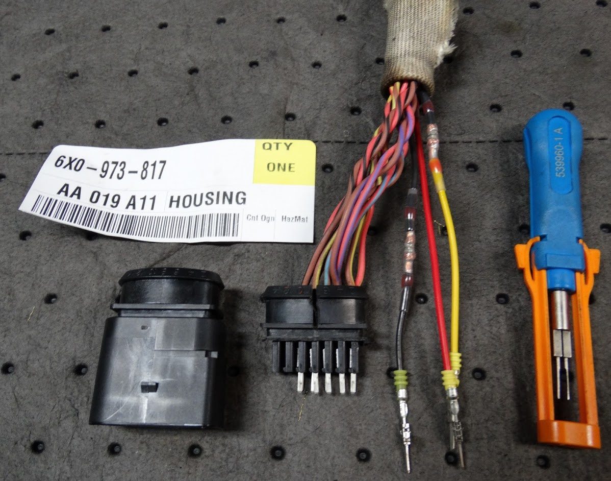
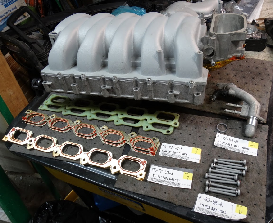
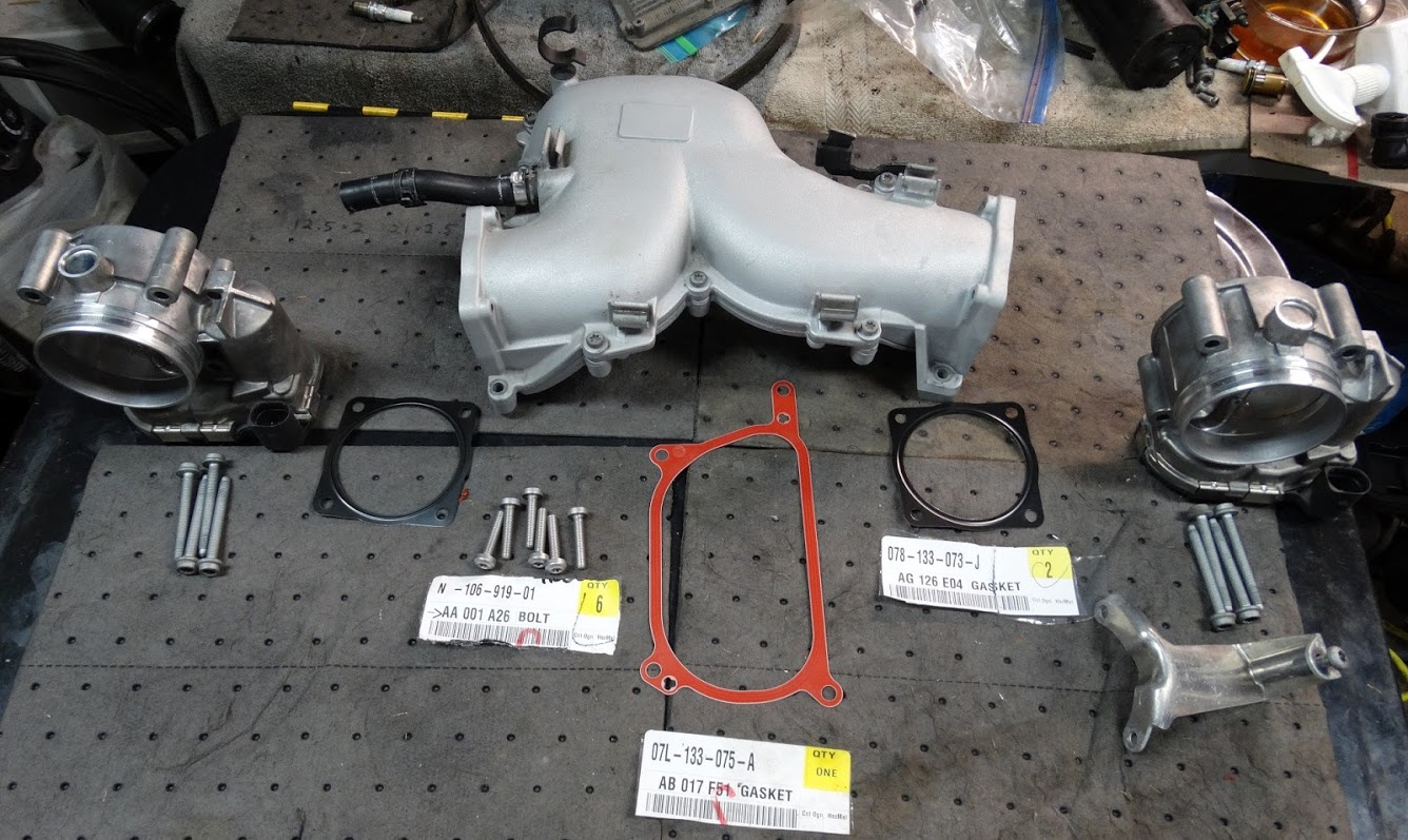
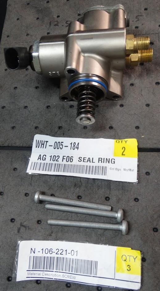
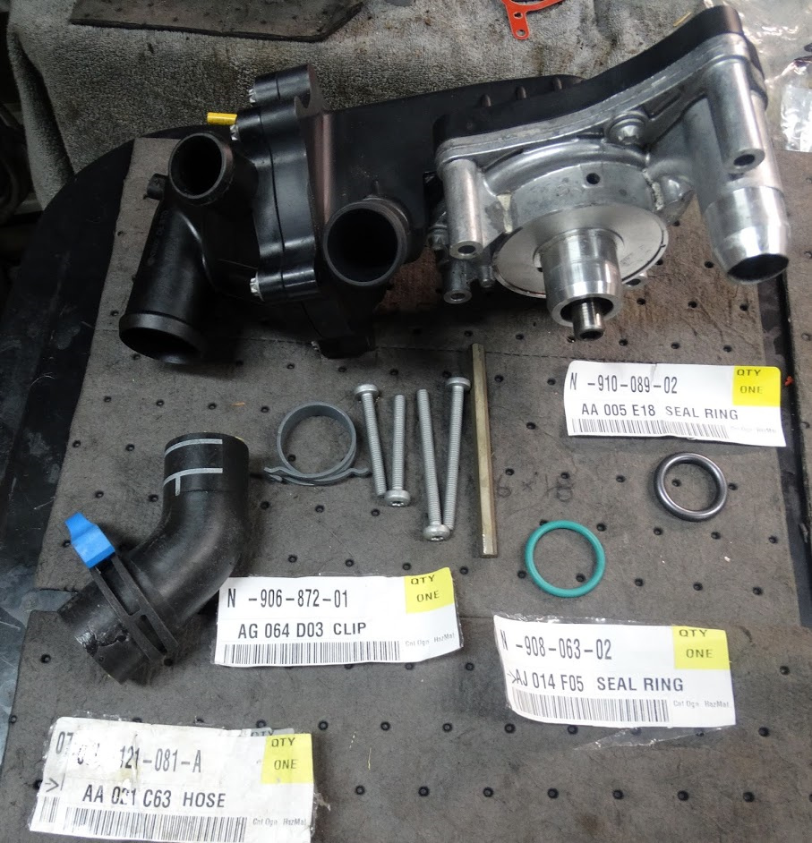
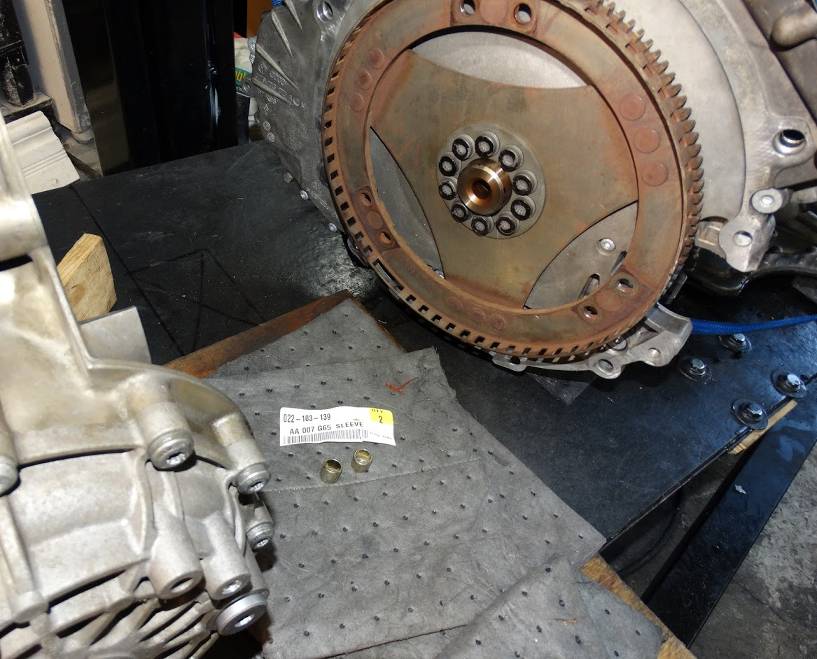
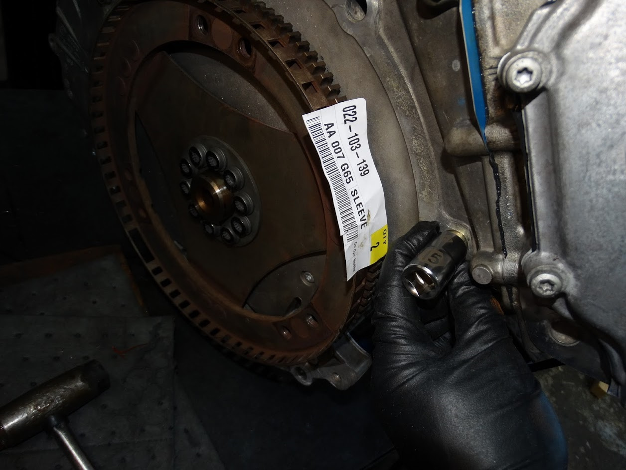
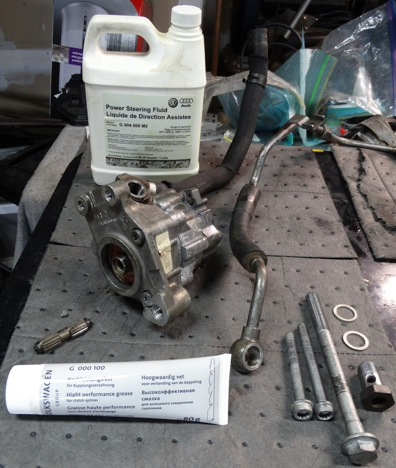
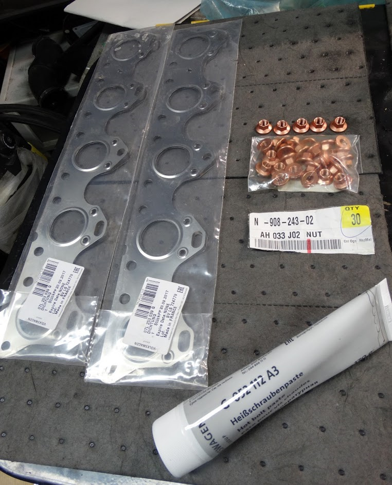
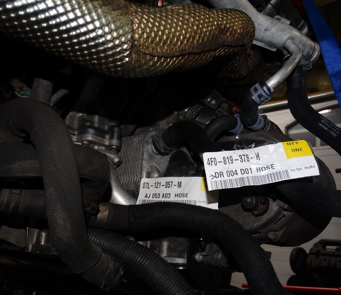
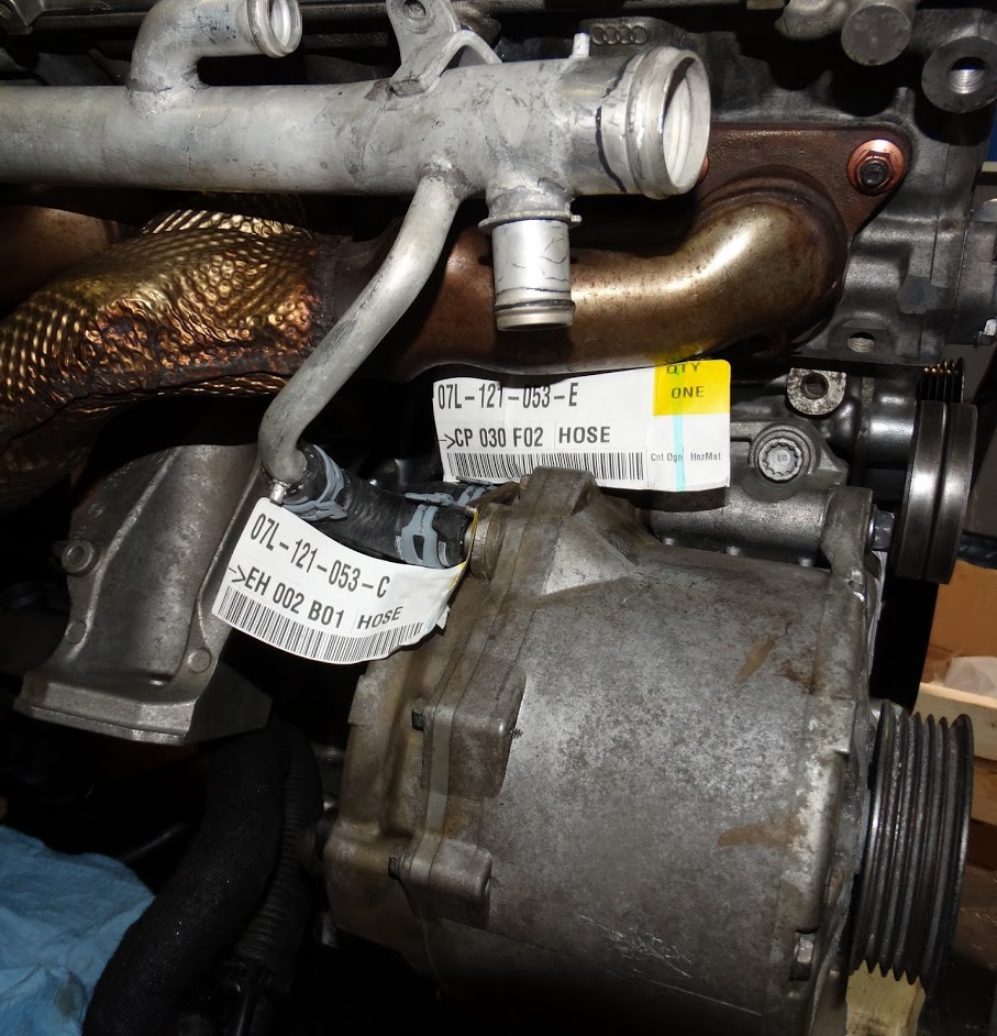
Here are pretty well all of the parts I have received so far.

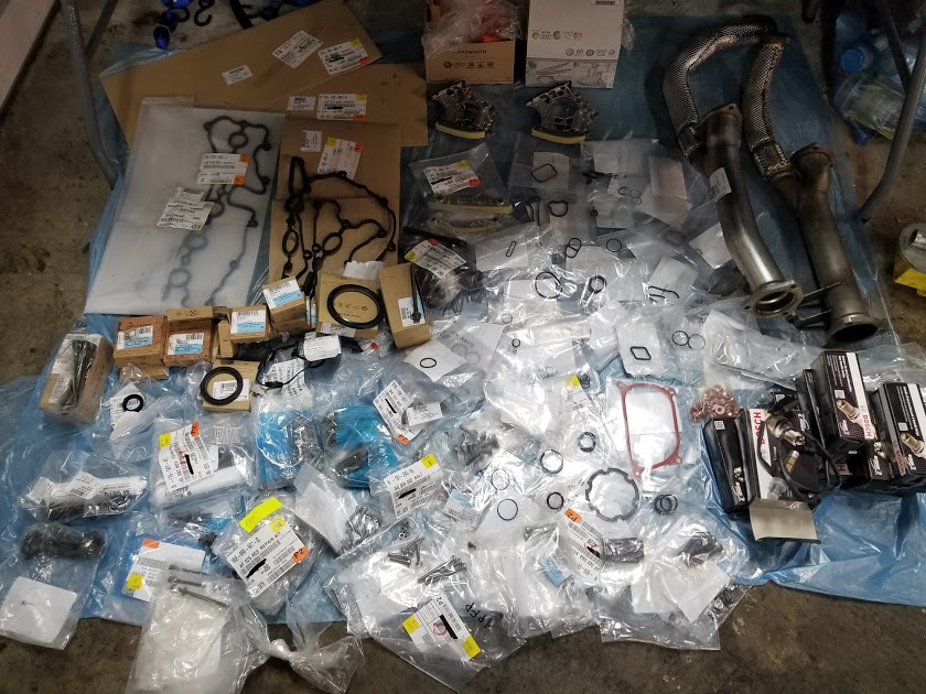
There are a few items there that do not have to be replaced when overhauling the engine.

I am just replacing them because it is so much easier to do with the engine out.

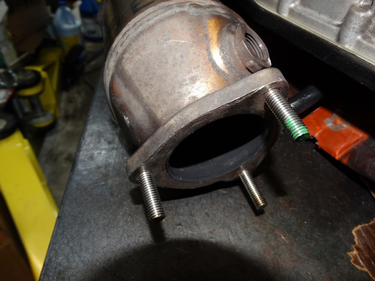
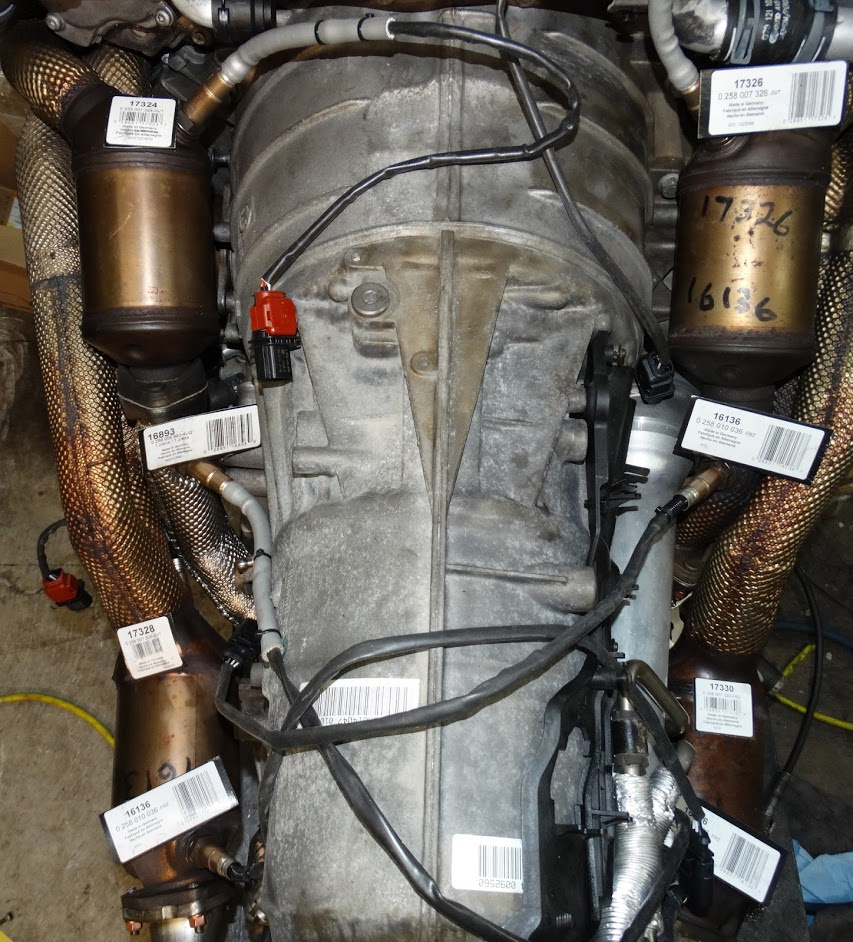
The small flex sections in both of my y-pipes had rotted out so I decided to replace those. The right side can be done with the engine in the car. The left side cannot.

I am also replacing all eight O2 sensors because they are not that expensive and I believe 6 of the 8 require an engine drop to replace anyways.

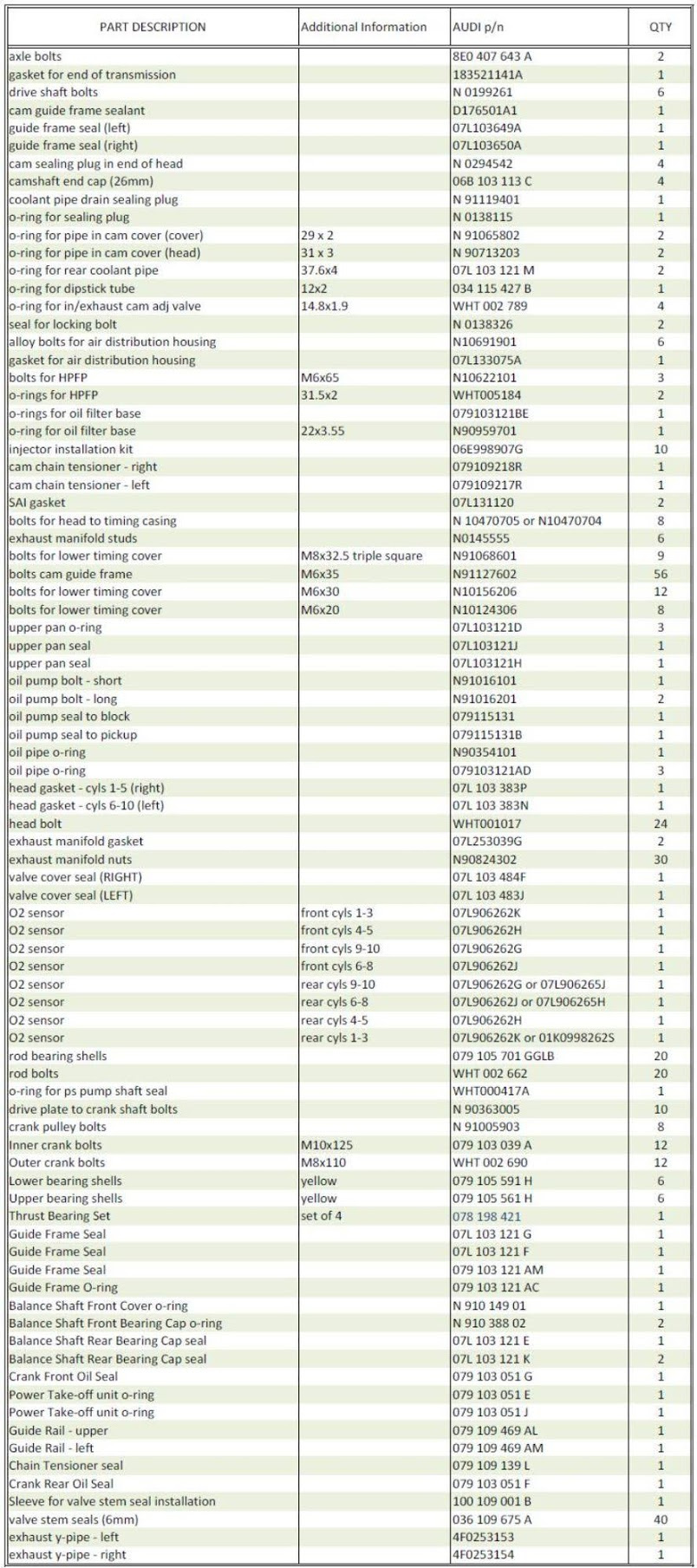
Here is a list of everything with p/ns and descriptions. There are 85 different parts which, with the multiple quantities required for some parts, combine for a total of 400 parts.

I apologize for the size of the text. From what I can tell, this forum does not allow either the height or width of an image to be greater than 2000 pixels. I will reformat it into two columns in a later post.

There has not been much progress in the last couple of weeks as I have been waiting on a few items to arrive. Our postal strike has certainly impacted my project timeline somewhat. I have come to the realization that this is probably going to stretch out over a few months so I broke down and bought a car cover to keep the elements (and bird crap) off the car over the winter.

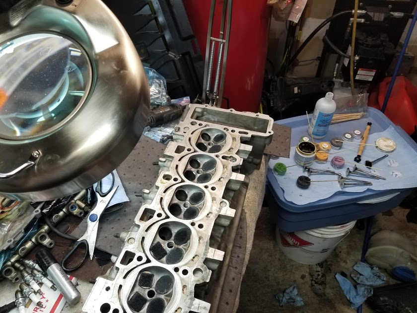
I was able to get one of the heads somewhat clean using brake cleaner and a nylon brush. A dremel was used with a few different shaped brass wire brushes to clean inside the intake and exhaust ports.

The carbon is gone at least until I start the engine.

Before installing the new valve stem seals, I checked the guides for excessive wear by measuring the valve tilt using a dial gauge.

They were all in the 0.010” to 0.020” range (0.25 to 0.5mm)

The specified limit is 0.8mm.

In the Bentley manual, if the valve guides are worn beyond the limit, they tell you to replace the head. The valve guides are not even identified in ETKA as a separately available part. It is a good thing there are several aftermarket companies that have them available.

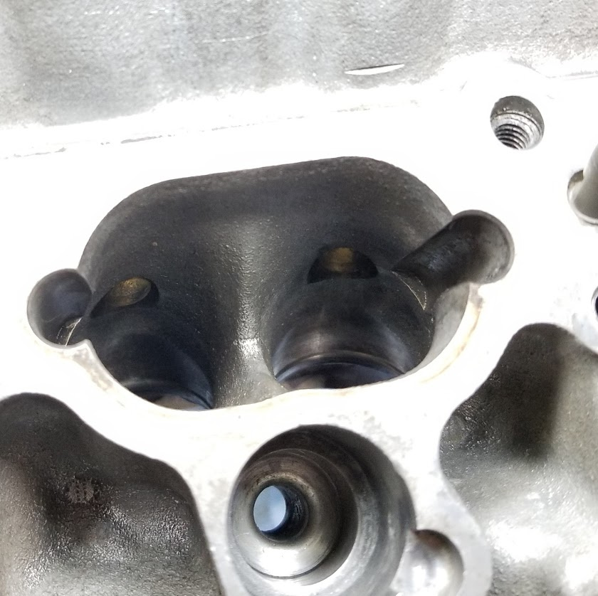
Each valve and seat were also checked for proper sealing using a layout marking method I found in a machinists forum. I originally started with a Prussian blue layout fluid but that was too messy and took too long to dry. A thick Sharpie marker will do the same job and is much easier to control where it goes. All the valve seats were covered with black marker and then hit for a few seconds with a heat gun to make sure it was completely dry so it would not smear.

The corresponding valve is then installed and rotated a few turns using a lapping tool. Ideally, there should be a uniform width area around the circumference of the seat where the marker has been removed through rotating contact with the valve. If there are areas where it remains, these are points of non-contact (“low spots”) and further lapping or grinding operations would need to be carried out.

I found minor pitting on pretty well all of the valve seats. The intake port on the right in the picture below was one that had the most significant pitting.

I just placed an order for a variety of different “grit” diamond pastes to do some lapping operations with. I ordered them from a Canadian vendor (who ships by Purolator) so I am hopeful they will arrive by the weekend.

The diamond pastes arrived this past Friday so I was actually able to make a little progress this past weekend.

The factory valves and seats have almost a mirror finish on them. My initial goal was to get something close to that as the smoother the finish, the more points of contact you have between the valve and the seat and the better the heat transfer. A true mirror finish would require polishing down to the sub-micron level. In my opinion, I do not think that is achievable in a home garage using the equipment that I have available in a realistic amount of time. I therefore decided that 7 micron (~2800 grit) was the finest paste that I was going to use.

Traditionally, I have always lapped valves by hand using a lapping tool which is essentially a plastic or wooden rod with a suction cup on the end of it. With 40 valves to do and multiple paste changes for each one, I figured I would look for a more efficient (ie. less manual) method of doing it. I saw there was a number of You Tube videos of various individuals using pieces of vacuum tubing stuck on the end of the valve stem with the other end in the chuck of a cordless drill.

I gave it a shot on the first valve and soon decided that it was not the method I wanted to use in my particular application. It would be ideal if you are just using a single valve grinding compound and had no need to clean the valve and seat periodically to check the progress. Two of the more subtle things I did not like about it were that the sound of the drill masked the sound of the grinding action and you have minimal feedback through the drill regarding the grinding as compared to when you do it by hand.

I also quickly found that the suction cup alone on the lapping tool was not going to be sufficient to adequately stick it to valve. Our intake valves have a concave center section and I found that no matter how well I cleaned and dried both the valve and suction cup, it would not stay stuck while lapping for more than about 30 seconds before it would begin to slide around. I tried spraying belt dressing fluid on the cup to soften the rubber a little but that only marginally improved things. I ended up sticking Velcro discs to the valves and screwing the mating Velcro section to the end of the lapping tool. That combination worked quite well.

Here is a picture of head with the “Velcroed” valves and the assortment of lapping pastes I used.

I initially started with a 40 micron paste and found it was taking longer than I wanted to get rid of all the pits on the valve itself. I switched to a valve grinding compound (using just light tool pressure) and that took care of all of the pitting in under a minute for just about all of the valves. I then progressively worked though the various “grit” pastes from 40 down to 7 micron.

As a check, after all the lapping was complete, I once again marked the seats with a Sharpie and checked for low spots. All of the valves (in this head) were found to have full seat engagement.

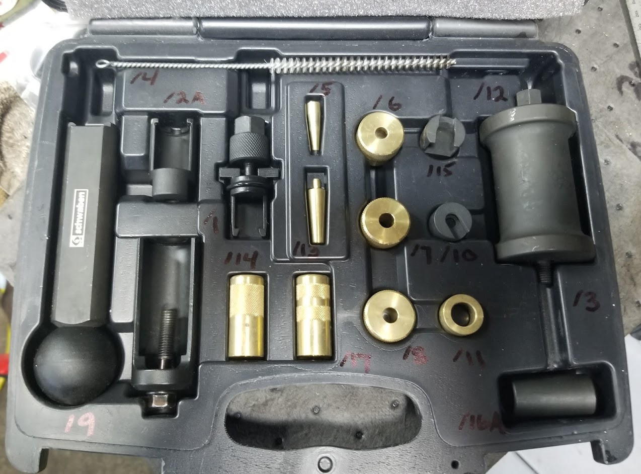
Next up was to install new stem seals. These just push on fairly easily with the use of an insertion tool. A little lubrication and a small plastic sleeve over the end of the valve were used to make sure the lip on the seal did not get damaged during installation.

Installation of the valve springs, discs and keepers is about the same as you would find on most DOHC engines.

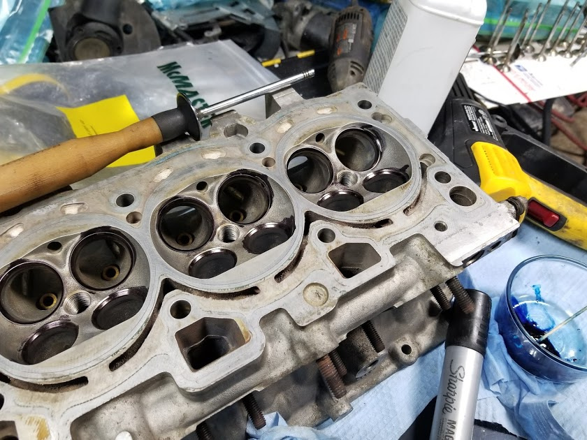
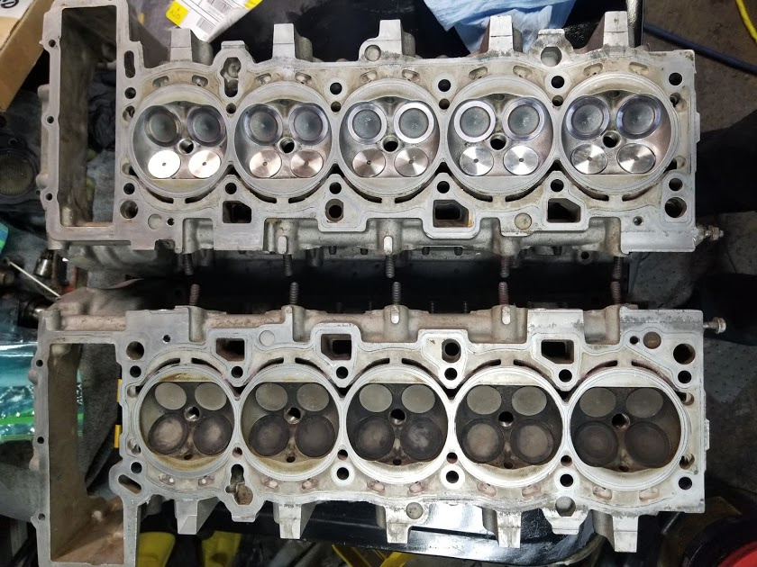
Here are a couple of pictures of the completed, clean cylinder head compared with the one I still have left to do.

I am going to wait until I get the heads bolted to the block before I install the cams. This way I can do a leakdown test without concerning myself if any of the valves are open. It is also a lot easier to torque all the cam guide frame bolts down when the head is bolted down to a block on an engine stand.

I am going to proceed with the other head next as there are some items I am still waiting on before I can move forward with the block.

The second head went much quicker than the first as I already had all my parts and shop supplies.

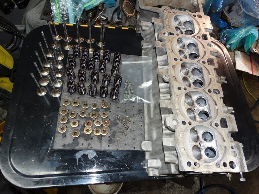
Here is a shot of the cleaned head with all 120 parts ready to be installed.

Here are both heads now complete and ready to bolt onto the block.

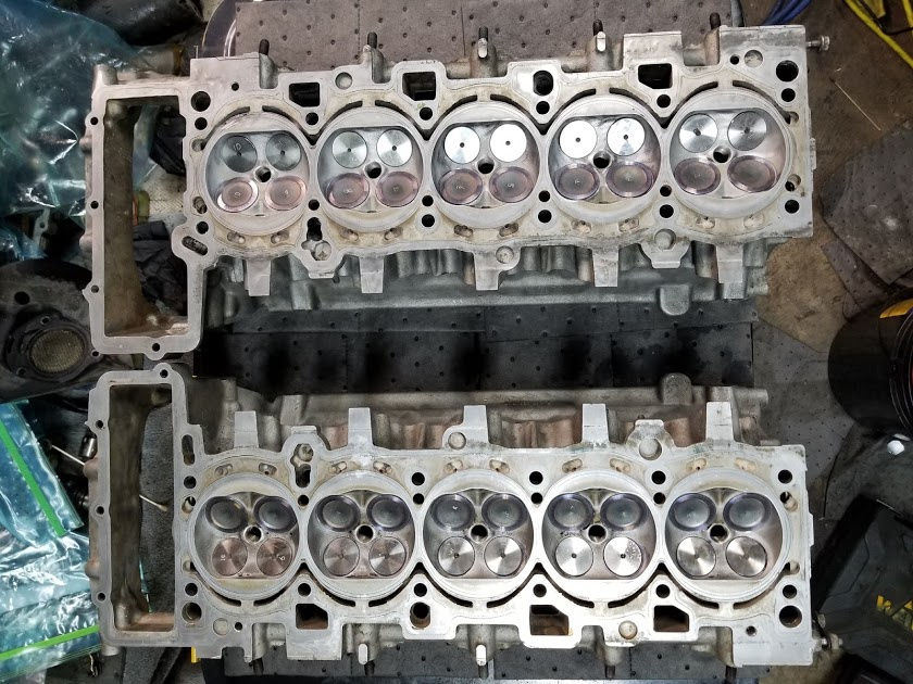
Too bad the block is not ready for them.

Now I have to take a break from this for a week or so to finish off some home reno projects before family starts visiting for the holidays.


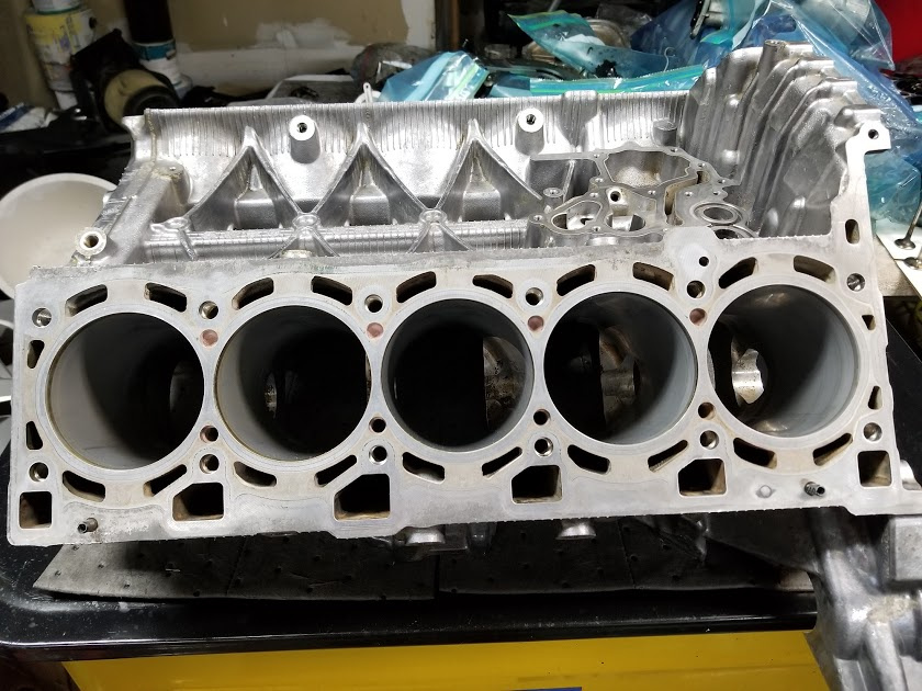
With the heads assembled as far as I can take them, it was now time to turn my efforts towards the block.

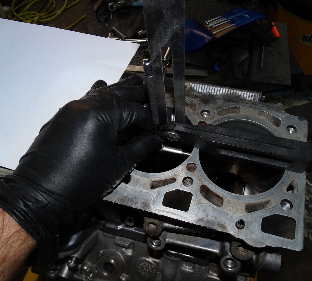
First up was to check both decks for flatness. Since neither head was warped as a result of the overheating, I really wasn’t expecting to find any surprises.

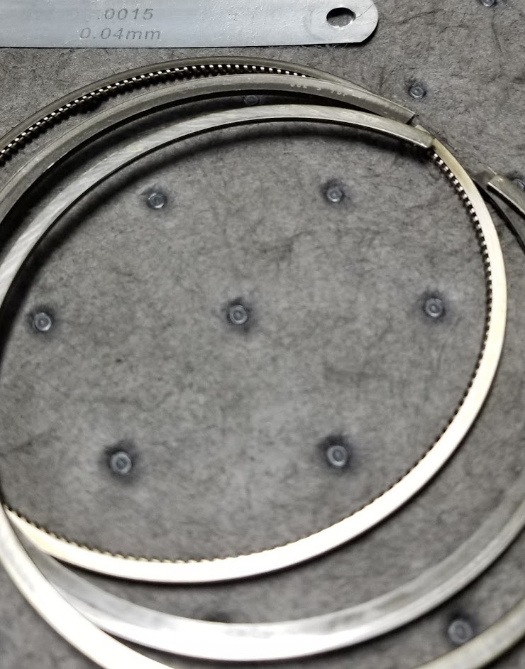
Using a precision ground straight edge and a set of feeler gauges, I checked the two decks for flatness in the 28 positions designated in the image below.

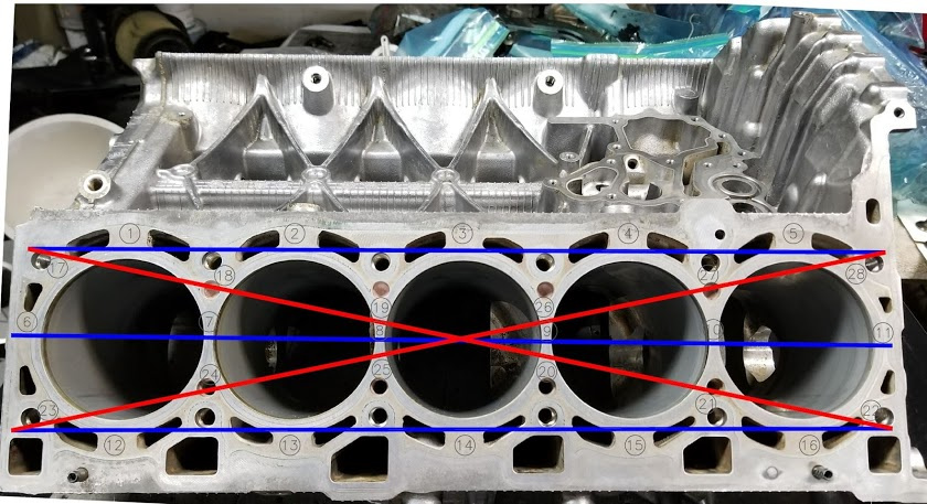
The thinnest gauge I have is 0.04mm (~0.0015”) which I was not able to drag out from under the straight edge at any of the measurement locations. I know they give a flatness limit of 0.1mm for the heads, I could not find a specification for the block in the Bentley manual.

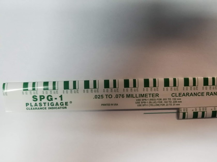
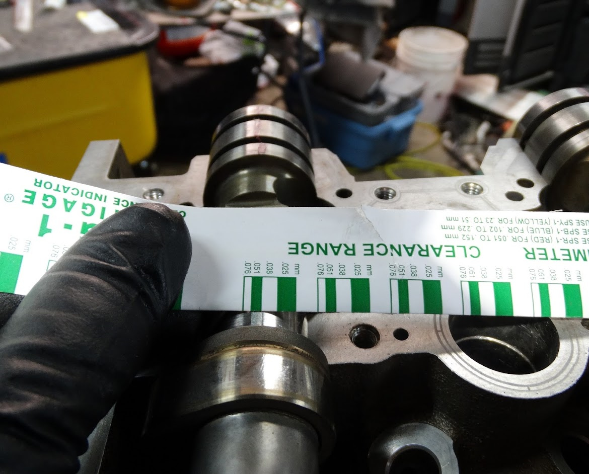
I am replacing all of the upper and lower crank bearing shells so the next item I checked was the radial bearing clearances. The quickest and easiest way to do this is to use Plastigage.

For those who are not familiar, it is a simply a strip of plastic with a cross section extruded to a very precise tolerance. It is available in different cross sections which each cover a range of radial clearances. For crank bearings, the package is green and it covers a range of 0.025 to 0.076mm

You cut it off in sections (the width of the bearing) and lay them on the top of each crank journal. The bed plate is then installed and the bolts tightened to 30 N-m (22 ft-lbs). The bed plate is then removed and you are left with flattened pieces of Plastigage sitting on the top of each crank journal. There is a width gauge printed on the side of the package that you compare the deformed section to. Obviously the wider it is, the less radial clearance you have.

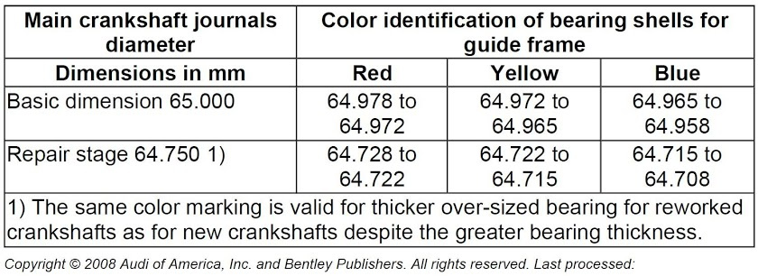
The bearing shells are available in different colors which represent slightly different thicknesses.

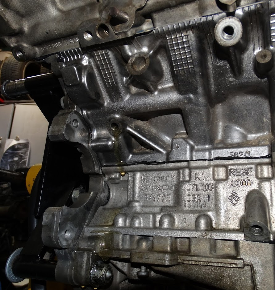
According to the Bentley manual, the color code for the each of the six upper bearing shells is supposed to be stamped into the side of the block up at front on the left hand side.

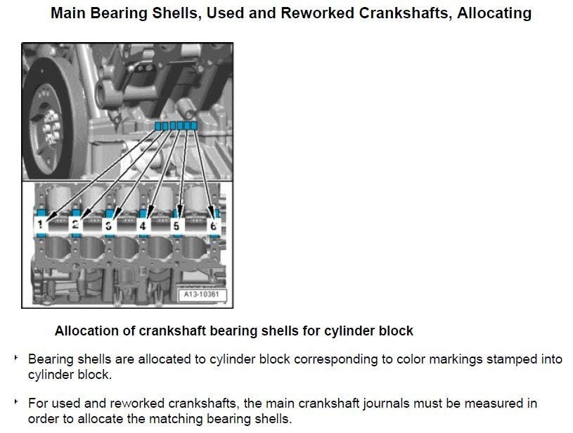
I could not find any six letter stampings anywhere on the block. The next place to check was the original bearings themselves as they should have a paint marking on the side of them (either blue, red or yellow). I believe all the cleaning I did with the heavy solvents must have dissolved any paint marking that may have been on them. The ETKA system at the dealer does not have the bearing colors for specific VINs either.

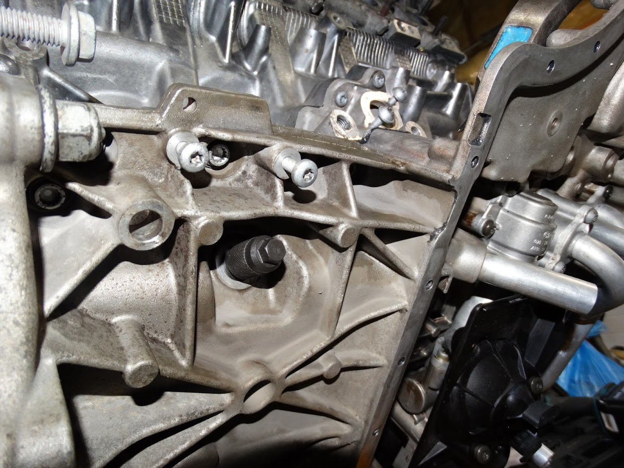
I decided at this point to take a little bit of a leap of faith as the code GGGGGG was stamped into the face of the counterweight on the end of the crankshaft

29 - http://audirevolution.net/addons/albums/images/359247243.jpg

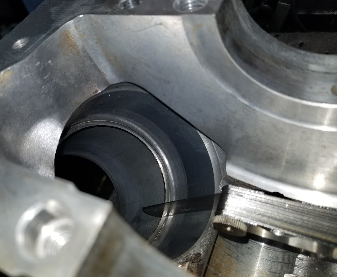
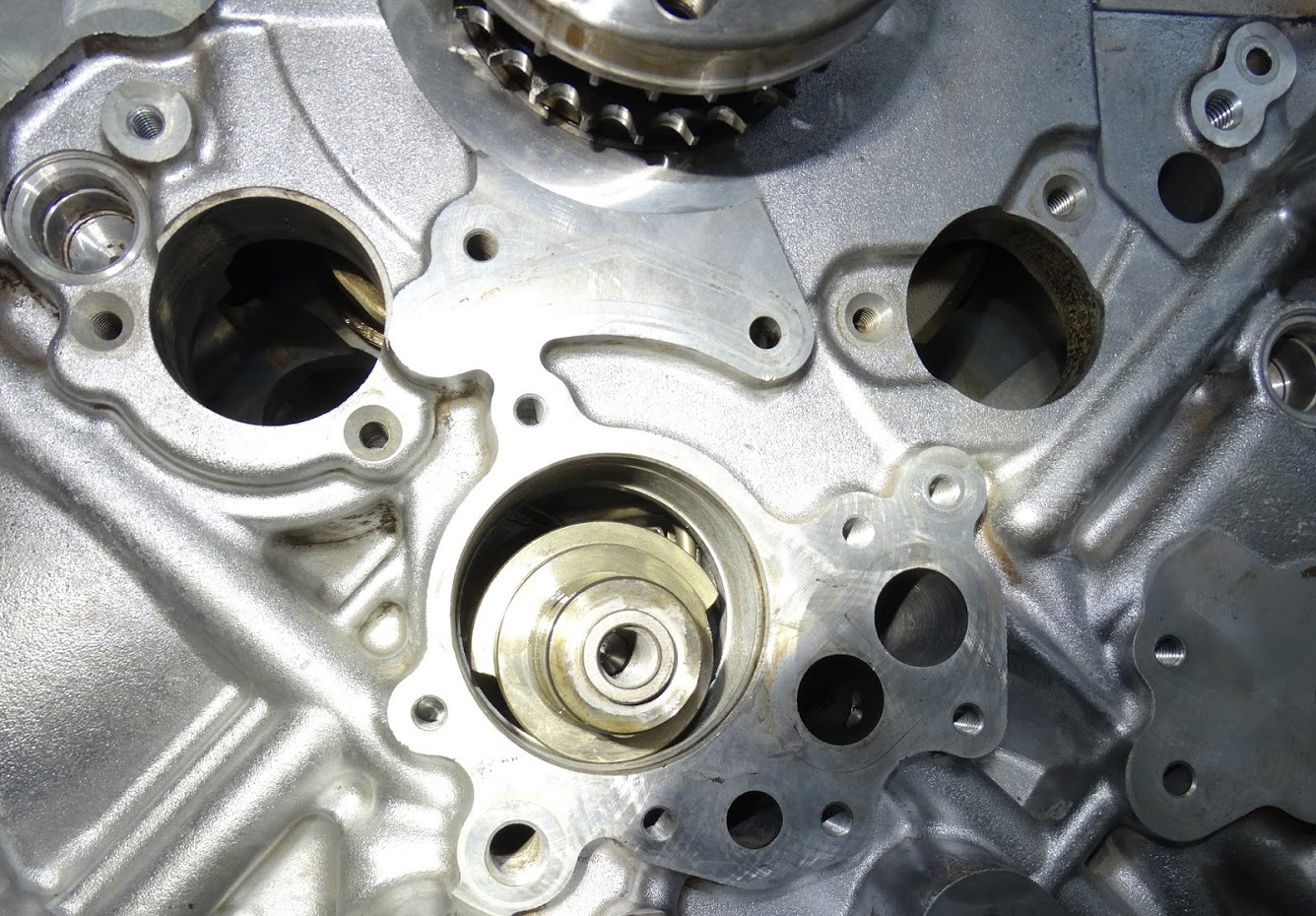
and there were also “G”s stamped next to each journal on the bed plate (circled in yellow below).

“G” is the code for yellow.

According to the Bentley manual, both of these locations are for the lower (bed plate) bearing halves. Without any better information available at the time, I decided to order yellow for both upper and lower and see what the results of the radial measurements showed. The bearing shells are relatively inexpensive so if I had to get six new upper ones, it would not be a big deal.

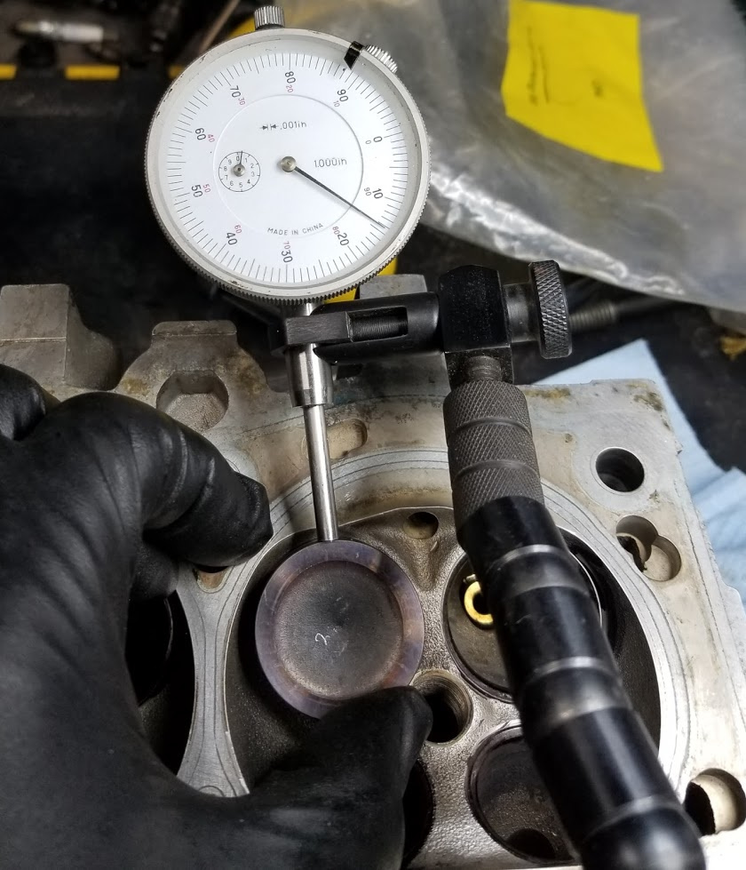
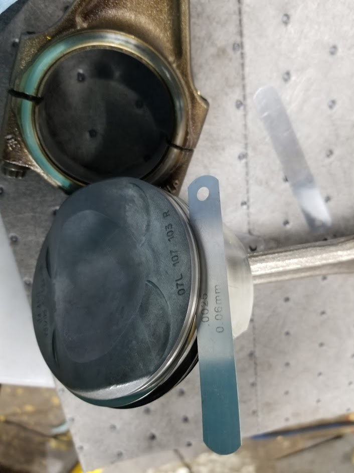
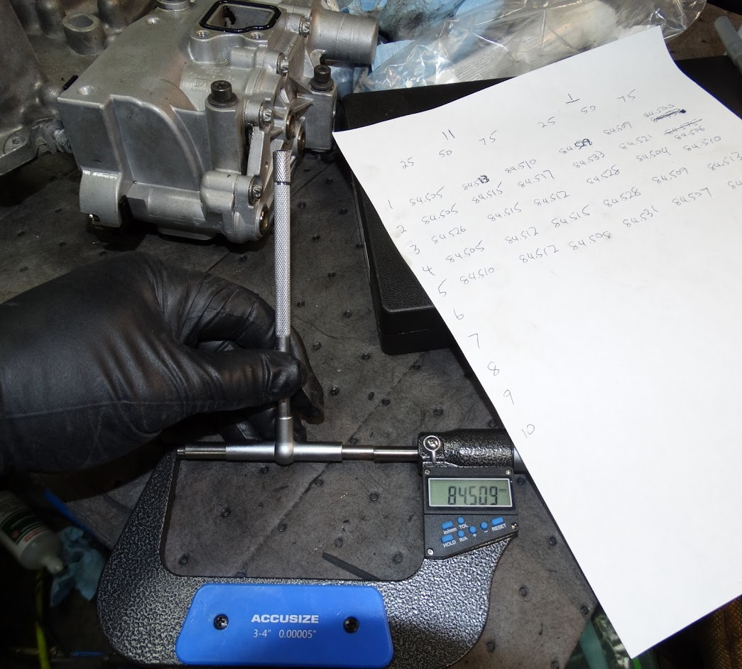
The radial clearance measured using the Plastigage on the crank bearing journals was in the 0.076” mm range for all six journals (picture below).

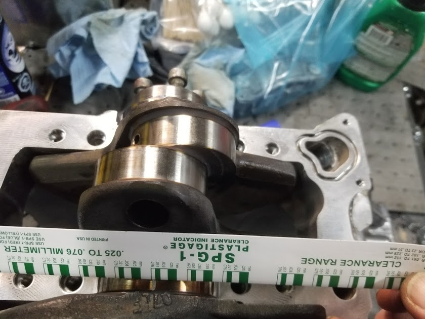
The Bentley manual specifies a radial clearance of 0.017 to 0.044 for new and a wear limit of 0.08 mm. Mine were all too close to the wear limit for my liking so it was time to get a precise measurement of the actual journal diameters and select bearing shells accordingly.

I measured each journal at two different locations around the diameter and found all twelve measurements to be in the range of 64.960 to 64.964mm.

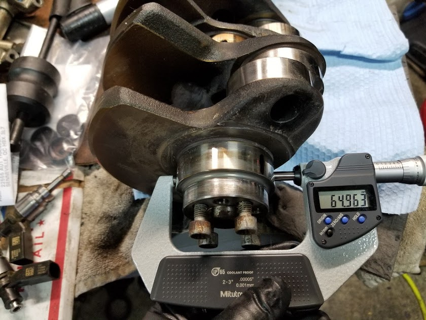
Using the chart in the Bentley manual, this corresponds to the “blue” bearing shells.

I had new “yellow” ones installed for my initial radial clearance measurements.

Of course when I called up the Audi dealer, the “blue” ones have to come from Germany. The “yellow” ones I purchased initially were in stock at the local warehouse.

With the holidays upon us, this adds another two to three week delay to the project.

Unbeknownst to me, the parts guy at the local dealer rushed the “blue” bearing shells in for me UPS red. I was not expecting to see them till the second week of January but he called yesterday to say they had just come in. With a four day weekend ahead of me, I am hoping to make some good progress.

Last night, I swapped out the yellow shells for the blue ones and re-checked the radial clearances using Plastigage.

Below is a comparison of the difference in the width of the compressed Plastigage pieces between the yellow and blue bearing shells. The Plastigage using the blue shells is noticeably wider. It was consistently in the 0.051mm range across all six journals.

The increase in bearing shell thickness resulted in roughly a 30% reduction in the measured radial clearance which puts them much closer to what would be expected in a new engine.

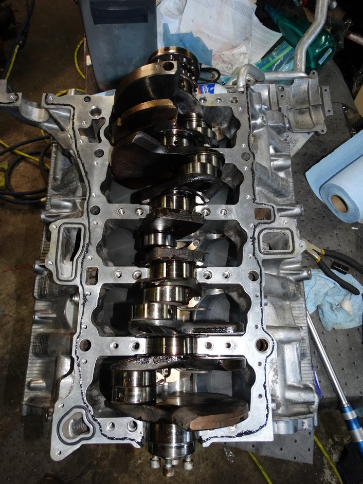
The last clearance to check prior to commencing the assembly of the bottom end is the axial play in the crankshaft. The Bentley manual specifies that the axial clearance should be in the range of 0.090 to 0.158mm.

In the picture below, you can see that the axial clearance is 0.004” (0.102mm). The measured clearance being at the low end of the specified range is a direct result of replacing the thrust bearing set.

Now I can finally move along and start putting the bottom end back together.


I will post more portions of the thread as I track down the rest of the pictures

4 Likes

I was not able to edit the first post to add the remaining pictures so this second post goes through the complete assembly process and stops at a point where the engine is ready to go back in the vehicle.

Edit - I just found out the body of a post is limited to 32000 characters and this was going to be 45000. At least it did not crash when I tried to post it.


Dec 29th, 2018

I managed to get a few hours to work on this today.

First up was to install the five piston oil spray nozzles in the block. Here they are with the fifteen bolts.

The bolts are installed using a high temperature, medium strength threadlocker (loctite 246). The 7649 primer is just used to speed up the cure time.

I re-used the original bolts. If I had to do it again I would buy new ones as it would be much cheaper given the amount of effort required to remove the old thread locker residue from the bolt threads.

I ran an M6x1 tap through all of the threaded holes in the block to remove as much of the original thread locker residue as possible.

Here is a shot of the nozzles installed.

Next up was to assemble the block, crankshaft and bed plate together.

Here is a shot of the bolts, seals and bearing shells (upper and lower) that were replaced along with the Loctite 5970 silicone flange sealant that was used to seal between the block and bed plate.

In addition to the 24 bolts shown above, there were 28 other 6mm bolts of varying lengths that are used to attach the bed plate to the block.

Here is a shot of the block with the bearings and seals installed. The bearings have been coated with oil to minimize friction during the first initial crank of the engine.

Here is the crankshaft, with the journals oiled, installed in the block. A bead of sealant has also been applied. It is certainly not the neatest application job but at least there are no gaps and it is where it is supposed to be.

Here is the lower bed plate with lower bearing shells installed and oiled

The block, crank & bedplate assembled

The tightening sequence for the 24 torque to yield bolts is done in a very specific order in several stages. I will refer you to the manual for the specifics

The last job for the afternoon was bolting the baffle plate to the bottom of the bed plate. It is attached using 21 bolts (which were re-used) that also have a very specific tightening sequence.

That is it for today.

I had hopes of getting the PTO unit and the drive chain installed on the back of the engine today so I can install the lower timing cover. This is necessary so I can get the engine back on the stand and start working on the top end stuff.

Those hopes were dashed when I discovered I was missing a small o-ring that goes between the PTO and the end of the block. I do not recall seeing it when I removed the unit. It is quite small and it may have just fallen on the floor when I separated the unit from the block. The problem is I do not see it in the online ETKA diagrams so I am going to have to make a trip to the dealer to look at their parts database. With New Years on Tuesday, this will likely delay the continuation of the assembly process until the end of the week.

Last week while I was waiting for the crank bearing shells to come in, I carried out the following series of measurements on the piston and ring assemblies.

  1. piston diameter
  2. piston ring end gap spacing
  3. piston ring side clearance

Since my initial compression and leakdown numbers were all pretty good, this was more of an academic exercise.

Measuring Piston Diameter

The nominal piston diameter is specified in the Bentley manual as 84.490mm. This includes a 0.01mm thick anti-wear coating on both sides. The minimum measurement is given as 84.460mm

I measured each piston 15mm up from the bottom of skirt perpendicular to the pin. My range of measurements was 84.463 to 84.475mm

While doing the measurements, I noticed that some anti-wear coating on one side of some of the pistons was completely worn off. The picture below shows the piston on the left with the wear coating substantially intact while the one on the right is completely gone.

Measuring Ring End Gaps

The ring end gap is a very important measurement when engine building. Too much gap and you will have excessive blowby; too little end gap and the ends will touch as the engine heats up. This can lead to catastrophic engine damage.

To measure the end gap, the ring is pushed down squarely in the cylinder bore (till it is about 15 mm from the bottom of the bore) and the gap between the ends of the ring is measured using feeler gauges.

The specified ring gaps (new rings) and the range of those measured are:

1st compression - 0.20 - 0.35 mm (new) limit 0.80mm measured 0.35 min to 0.55 max

2nd compression - 0.20 - 0.35 mm (new) limit 0.80mm measured 0.60 min to 0.65 max

Oil scraper - 0.20 - 0.40 mm measured 0.38 min to 0.45 max

Measuring Ring Side Clearance

To measure the ring side clearance, feeler gauges are inserted between the top of the ring and the groove.

The specified sides clearances (new rings), limit and the range of those measured are:

1st compression - 0.035 - 0.085 mm (new) limit 0.20mm measured 0.06 min to 0.07 max

2nd compression - 0.005 - 0.045 mm (new) limit 0.20mm measured < 0.04mm

Oil scraper - 0.01 - 0.05mm (new) limit 0.15mm measured < 0.04mm

This is just a note for installing piston rings. The profile of our rings is non-symmetrical so it is important to get the correct “side” facing up. The word “TOP” is etched into the side of the ring that is supposed to be oriented towards the top of the piston

I still intend on measuring the cylinder bore diameters but that is going to have to wait till I get the engine mounted on a stand.

While waiting on the o-ring for the PTO unit to come in, I figured I would install whatever other components in the back of the engine that I could.

The balance shaft was first on the list.

Below is a picture of the balance shaft with the end bearing housings and the six seals/o-rings that are being replaced.

When installing the balance shaft in the block, care must be taken not to damage the piston oil spray nozzles. They are in quite close proximity to where the balance shaft rotates. You can see them in the picture below just above the balance shaft.

In order to minimize engine vibration, the angular orientation of the balance shaft must be set in relation to the crankshaft. To do this, a special setting tool (VAG T40128) is used.

In the picture below, you can see there is an offset slot in the the front end of the balance shaft. This tool is bolted in through the front end bearing holes to hold the shaft in a specific orientation.

Once the drive chain is installed and tensioned on the rear of the engine, the crankshaft is set to TDC and the sprocket on the rear end of the balance shaft is torqued down.

I will post up a picture of the rear of the engine once I get the PTO, tensioners and chain installed.

In a previous post, I showed a picture with the baffle plate installed under the crank. Clearly that cannot be installed prior to installing the pistons so I had to spend a couple of minutes removing it. I am a newbie here so I cannot edit my posts to remove the picture. I hope it does not confuse anyone.

I have been waiting on some bolts and more seals to come in so I can finish off the rear timing gear but a mix up in the picking at the local Audi parts warehouse delayed that for another couple of days.

With another weekend here and the desire to keep this project rolling, I decided to temporarily mount the engine on an engine stand so I could at least do some work requiring deck side access.

First up was to measure the cylinder bores to make sure they were within tolerance. As with the ring gap measurements, this was also an academic exercise given the respectable compression and leakdown test results that I had prior to the teardown.

Since I do not have an inside micrometer for measuring cylinder bores, I used a telescoping gauge combined with an external micrometer for measurements.

Here is a shot of the telescoping gauge inserted in the cylinder bore. A square was used to make sure the gauge was positioned normal to the wall of the cylinder.

For each cylinder, bore measurements were taken at 25, 50 and 75mm down from the deck surface both parallel and perpendicular to the axis of the crankshaft.

The Bentley manual gives a nominal bore diameter of 84.510+/- 0.005mm and a maximum deviation from the nominal of 0.08mm

The majority of my measurements were within the nominal tolerance range which would indicate negligible wear. The largest bore measurements I obtained were the ones closest to the deck surface measured perpendicular to the crank. The largest of these was found to be 84.533mm which was well within the maximum allowable deviation.

With the bore measurements complete, the next step was to install the pistons back into their respective bores.

Below is a picture of the piston and connecting rod assembly along with the new bearing shells and rod bolts. The original shells have also been included to show the typical wear pattern.

Although the piston rings rotate during engine operation, it is standard assembly practice to stagger the end gaps by approximately 120 degrees prior to installing the them back in the block

Note the arrow on the top of the piston which is to point towards the front of the engine when installed.

A standard band clamp type ring compressor was used to compress the rings to allow the pistons to be slid into their bores. A wooden block was used to gently tap the pistons in.

When the connecting rod caps are installed, the molded-in tabs on the pairs of rods sharing the same split crank pin must point towards one another as shown in the picture below.

With the new rod bearing shells installed, the last step was to check the radial clearances. Using Plastigage, I estimated the clearance for the set shown below to be approximately 0.044mm. This is midway in the range for new bearing/rod combos (0.020 to 0.069mm) that is presented in the Bentley manual.

I was only able to get two pistons (cyls 1 & 6) installed before my budgeted time ran out so I will

continue with the rest this later in the week.

The other eight pistons are now installed and the rod bolts torqued. The radial clearances were checked for all and found to be within the range for new bearing/rod combos.

Next up was the installation of the upper oil pan.

Here is a shot with the three o-rings, bolts (originals) and a bead of flange sealant applied

Upper oil pan installed and all bolts torqued diagonally in two stages (5Nm & 14Nm).

Here is the oil pump, pipe, all new seals and bolts. The bolts are torqued to yield so they must be replaced.

Oil pump and pipe installed

The engine was taken off the stand at this point so I could continue working on the rear end pto unit and drive sprockets

Here is the PTO unit with replacement seals and bolts (original). The seals for the a/c compressor and the power steering drives look nearly identical but they are actually directional as the two shafts turn in opposite directions.

The seals have been installed by pressing in using a socket with an appropriate diameter. Flange sealant is applied around the two drive shaft towers where they pass through openings in the block/guide frame assembly.

Here are the drive chain sprockets and the new tensioner and guide tracks. All of the original plastic guides were either severely worn or broke when I removed them because they had become quite brittle.

Here is the current state of assembly. I was able to install the sprockets but all of the chain guide and tensioner bolts are torque to yield which are currently on backorder at my local dealer.

Just a quick update today.

The tensioner and guide bolts finally came in so I could finish off the rear drive and timing chain components

Here is a pair of before and after shots. What a difference three months makes.

Next on the to-do list was to install the lower rear timing cover. This will allow me to get the engine properly mounted on a stand so I can start working on the top end.

Here is a shot of the rear cover parts. The twenty 6mm bolts are torque to yield so they had to be replaced. I just cleaned the 8mm ones and re-used them.

I was thinking of pre-installing the rear main seal with the cover off as it would be very easy to press it in without the crankshaft in the way. I decided against this plan when I noticed that the seal lip is at a backwards angle. This requires that the seal be expanded to the shaft diameter using a tapered tool and then slid off onto the crankshaft. I did not have anything lying around with a suitable profile to do that with so I decided to leave the seal install till later.

Here is a shot with the cover installed. I intentionally installed it with the engine upside down. You want to make sure the chains for the cam gears are hanging free when you seal the cover up. It would really suck if the chain(s) got wedged inside the casing and you did not discover it until you already had the heads on and went to install the cams.

I decided to let the sealant cure for a day before placing the engine on the stand and rotating it 180 degrees. I used quite a bit of engine oil when I installed the timing components and did not want that running down the inside of the casing and contacting any uncured sealant.

This gave me some time to load up my injectors with new seals and get them installed in the heads.

This may be common knowledge but I only realized about a month ago that the injectors have date codes printed on them.

Here is my collection of 19 injectors ranging in age from 2006 to 2017.

I would have 20 but I broke one about three years ago when I was pulling them out to get them cleaned. If you look closely, there is a six digit (DDMMYY) date code on each one. My vehicle is a 2007MY so I know that at least one was replaced probably sometime in 2009. I bought three new ones to replace the three originals that I was still running when I started this project.

I purchased this injector service kit about three years ago and I have found it very useful for removing and installing injectors as well as installing the Teflon combustion chamber seals.

Here is a shot of the ten injectors ready to be installed.

They just push straight into the head using the tool in the service kit.

I find if you just rotate them ever so slightly back and forth as you are pushing, they go in with a lot less effort.

After giving the sealant time to cure, the engine was mounted on a stand. It was finally time to get the heads installed.

Here is a shot of one of the heads with the new head gasket and bolts.

The bolts are tightened in four stages (30, 60Nm, +90deg,+90deg) working from the middle of the head diagonally outwards to the ends. The bolts started yielding part way through the second 90 degree stage of the tightening sequence.

It is finally starting to look like an engine again.

Now that the cylinders were sealed, I decided to re-run the leakdown test. The engine is cold so I expect to see quite a bit of leakage past the rings but hopefully nothing past the valves. The cams are not in yet so I do not have to be concerned with making sure I am on the compression stroke for any given cylinder. However, you still want the piston to be at TDC or BDC as you do not want any unexpected rotation of the crank when you pressurize the cylinder. This could wreak havoc with the cam chains loose in the timing cover. I chose to go with TDC as my cylinder bore measurements were marginally larger towards the top of the bore. Also, my previous testing was all done at TDC so it would make for a more logical comparison.

I installed the fuel rails on the off chance that the 100psi test pressure would be enough to push an injector out of the head. It is acting on a very small area but I rather be safe than sorry.

When I first started increasing the test pressure on cylinder 1, I was a little concerned as I could hear a lot of air coming out of the crankcase (no lower oil pan installed) and the cylinder holding pressure was lagging behind the test pressure by about 20 psi. Then all of a sudden once it hit about 70 psi, the sound level of the leaking air dropped dramatically and the holding pressure jumped about 15 psi. This sudden drop in air leakage was a result of the top compression ring being pushed out by the air pressure to seal against the cylinder wall. I had never seen such a sudden change in leakage pressure before. All of the cylinders exhibited a similar behavior at some point as the test pressure was increasing between 50 and 80psi.

Once the rings had “seated”, all of the cylinders showed a consistent leakage of just 5%.

The main goal this past weekend was to get all of the cams installed

The first thing you want to do before even thinking about installing the cams is to set the engine to the “TDC” position and install the crankshaft locking pin (3242) . Black pin in the picture below.

I am not sure why they refer to it as the “TDC” position because piston#1 is down at least 85mm from TDC when the locking pin is installed.

Doing this is absolutely key as you do not want to try and install the cams with the crank in any other position as you may end up ramming a valve into the top of a piston as you are tightening the cam guide frames down.

What would a progress update be without more measurements???

The only measurements I was interested in checking were the radial clearances in the cam journals. There was visible scoring in the aluminum bearing surfaces and I wanted to see if the clearances were still within acceptable limits.

To measure the radial clearances in the cam journals, the cams were placed on the heads without any rockers or lifters installed. Green Plastigauge strips were placed on the cam bearing points and the guide frame was installed. The bolts were torqued in sequence to 8Nm and then removed again. This procedure was carried out on both heads. Below is a shot of the squashed Plastigauge showing a bearing clearance in the range of .051mm.

This was consistent across all ten bearing journals. The Bentley manual specifies a clearance range of 0.024 to 0.066mm. I am towards the upper end of this range. There are no replaceable bearing shells at this location, so the only options are to either leave it be or replace the heads. Needless to say, I went with the former.

Here are all the components laid out for installing the cams on one side. The bolts are all torque to yield so they had to be replaced.

The cams are first placed in the guide frame and the camshaft locking clamp (T40070) installed to hold both cams in a specific orientation.

The notorious “oil in the spark plug tube” seal installed and sealant applied.

There are no fixed alignment pins to set the cam guide frame in place on the top of the head like you have with the cylinder heads and upper oil pan connections to the block. Short pins such as these would not be much use as there is a fairly substantial gap between the two when you first position the guide frame in place as all the valves are closed.

Audi provides a pair of matching close tolerance holes in both the head and the guide frame for precisely aligning the two parts together. I purchased the VAG alignment tool (T04116) to do this with. It is such a close fit that I had to run a brass pencil brush on my dremel through all four holes individually in order to strip off the thin layer of oxide that was preventing the tools from being inserted. Even then, it was a very close fit just to get it through the hole in each separate part. It needs to be very precise as each part forms half of the bearing journal that the cams ride in. The aligning tools are left in until all the bolts are torqued down and then you use the mini slide hammer out of the injector service kit to get them out

Here is a shot of the alignment pins in place after all of the bolts had been torqued down.

I went to start on the other head when I discovered that the guide frame seal was broken where it goes around the end spark plug tube. I probably could have sealed the break with some polyurethane but I decided to wait another few days to get a new seal from Audi.

The next update will likely be the cam gears, chains and tensioners.

Here is a shot of the front and rear crank seals along with the four plugs that go in the ends of cylinder head (front of engine) in line with the cams.

Since I bought the car, the two on the left cylinder head were always slowly weeping oil just enough for airborne dirt to stick.

The Loctite 638 is a high strength retaining compound that is called out in ETKA under p/n D 154000A1

Here are the timing gears (original), new tensioners and bolts. The bolts are all torque to yield and had to be replaced. You will find that all of the 6mm bolts inside the timing casing are torqued to yield. It is the last place you would want a bolt to loosen up and fall out.

Here is a shot of the parts installed.

Note that the timing sprockets are not keyed onto the camshafts. You have to mark their orientation prior to disassembly and then reposition them the same way upon reassembly.

I still have to pretension the timing chains and torque the cam gears down properly. It is a lot easier to do with a second set of hands to hold the tension on the chains when the cam sprocket bolts are tightened.

For comparison purposes here are before and after shots of inside the LHS timing cover

When I first looked at the above two pictures, I was a little concerned as the sprockets are in completely different orientations. I then realized that the first picture was taken without the cam locking clamp installed and the engine was not in the “TDC” position.

Incidentally, the “TDC” positon when the crankshaft locking pin is installed is when none of the pistons are at TDC. This makes it safe to install the cams as there is no danger of the valves contacting the tops of any of the pistons.

Next up will be getting the rest of the engine sealed up (for oil) so I will be able to pre-oil it.

Work has been pretty crazy for the last few weeks so I have not had much time to move this project along substantially.

It is just as well as the rtv flange sealant takes forever to cure when the ambient air this time of year is so dry. I can keep the temperature in my garage at 20C (68F) when it is -20C(-4F) outside but the relative humidity is down around 20%. To cure properly, RTV sealants require moisture from the ambient air. I had to bring a humidifier into the garage in order to bring the RH% up into the 35 to 40% range for a few weeks so the sealants would cure properly. However, it is nice to work with rtv when the air is dry though as the working time is greatly increased. It is a nice change from trying to lay down sealant in the middle of August when the humidity is 90%+ and the stuff is skinning over almost as soon as it comes out of the tube.

I did manage to get a few items taken care of.

I torqued the cam timing sprocket bolts down with the assistance of one of my sons. A tension preload needs to be maintained on the chain while you tighten the bolt on each of the sprockets to an initial value. The cam clamps are then removed and a final tightening torque is applied to each bolt.

After the final tightening, the crankshaft locking bolt is removed and the crank is rotated 720 degrees back to the “TDC” position. The cam clamps and crankshaft locking pin are then re-installed. All bolts should thread in freely confirming that the timing is correct. The cam clamps are then removed but the crankshaft locking pin is left in place to facilitate the installation of the drive plate.

The rear timing covers were then installed with new sealing rings at both ends of the internal water pipes that bring coolant into the ends of the heads. The pipes were installed into the rear timing covers using a press

From my reading, these are known points of potential leakage although I saw no obvious signs that indicated this was the point that coolant was getting into my oil.

Next up was getting the valves covers on with new gaskets. I replaced the bolts (w/ seals) on the RHS. The LHS cover was replaced about three years ago so I reused the original bolts.

Here is a shot identifying the valve covers and o-rings for the cam timing valves and position sensors. ETKA does not identify the o-ring for the position sensors as a separate part so I measured them up (12mm ID x 2mm c/s) and purchased them from a local vendor.

Here is the oil filter base and seals along with the check valve and spray nozzle that are installed in the valley. I replaced the o-rings on those two components as well (12.5x2 for the spray nozzle and 21x2.5 for the check valve)

Next up will be a little reconditioning of the injector harnesses before I install the IM.

Feb 11th, 2019

1 Like

After being cooked for the last twelve years in the valley of the engine, all of my injector connector housings had become so brittle that I had them all held in place with zip-ties.

Replacement harnesses are ridiculously expensive so I decided to go ahead and just replace all of the connector housings.

Here is a shot of one of each of the types that can be found on the two injector harnesses.

Since I bought the car about three years ago, I have always had intermittent issues with the signal from the HP fuel sensor. Every once and a while, the engine would stutter for a split second.

The previous owner must have had the same complaint as I found a single wire outside of the factory loom going directly from the ecu connector to a second HP fuel sensor connector. The original connector was left attached to the factory harness but left disconnected in the valley. The person who did the wiring did a good job. All of the wires were terminated properly and the wire splices were tidy and sealed correctly. Initially, it did not make sense to me why I was still having this issue with the new signal wire run. Then I looked at the two wires for the sensor power supply and ground wire connections. The original two wires were left in the factory loom going from the black T14i connector back to the ecu. My guess is that when the tech was troubleshooting, they confirmed that the sensor power supply voltage and ground were good and all that needed to be replaced was the signal wire.

I did not like the look of this wire outside of the factory harness so I decided to replace the T14i connector. The tabs to release the secondary terminal lock were so brittle, they snapped off when I tried to release it so I ended up cutting the shroud off with a Dremel. When I exposed the male terminal pins, this is what I found. The three corroded terminal pins towards the bottom of the picture are 11, 12 & 13 which are the three for the HP fuel pressure sensor. Pin 13 is the most corroded one which just happens to be for the 5V sensor power supply. I am relatively confident that this has been the cause of my random stuttering.

Moving along, I pulled three new wires through the injector harness and spliced on the female terminal pigtails from the connector that was previously replaced. I spliced some new 1.5mm MT2 male terminal pigtails onto the other end to replace the corroded ones

With a little bit of harness tape, it should be almost as good as new at a fraction of the price.

Here is a shot of the harnesses installed in the valley before the intake goes back on.

Before I installed the intake, I figured it would be a good idea to put some oil into the pressurized part of the system to check for any leaks. In order to do this, I had to install the oil cooler which was the last component required to close up the lubrication system.

Here is a shot of the loose oil cooler and the two seals that often need to be replaced to resolve a common leakage issue that the engines of this vintage have.

For pre-oiling, I deliberately left the oil drain plug out so I could gauge roughly how much oil was left in the engine.

I screwed a mini-air line fitting into the port normally occupied by the oil pressure switch. To this I connected an old brake bleeding bottle that I have which uses air pressure to force fluid out of the discharge hose which would normally connect to the master cylinder.

I filled the bottle with oil and set the regulator at about 15psi.

The oil level started going down and after about 30 seconds, I saw a steady stream of oil coming out of a threaded hole in the block right behind where the starter sits.

It is a small 10mm plug that I had forgotten that I had even removed last October when I tore this thing down. It is the same type of plug that goes in the end of the front water pipe that you remove when you drain your coolant.

So I installed that and continued adding oil. I fed about 3L into it before it started coming out of the oil drain plug hole. No other leaks were observed and I confirmed that I had oil feeding the cam follower bores for the HP fuel pumps.

I am certainly glad that I went through this oiling procedure beforehand and found the open port when I did. This plug is behind the starter. For those that are not familiar, the first step in the Bentley manual for removing the starter is “Remove engine”.

Next up was installing the intake.

Here is a shot of the intake with spacers and gaskets/seals. The spacers require the use of longer bolts so I went with some 10mm longer ones and stainless steel washers.

Here is the intake installed.

I have never had any issues with vacuum leaks on mine but I remember the question of the intake bolt installation torque being brought up before by someone who was experiencing leaks.

The second gasket and spacer material adds compliance to this sandwiched connection. Therefore to achieve the same bolt clamping force, one would expect to have to tighten the fasteners beyond the specified 90 degrees after the initial 9Nm is achieved.

Of course I did not think of this until after I had the intake installed. If I were to go back and do it again, I would install the intake without the spacers and measure what the peak installation torque was for each bolt after the 90 degree tightening. I would use the average of these measurements as a basis for installing the intake with the spacers. Of course a bit of judgement and “feel” need to be used here. If you feel the bolts yielding and you are not reaching the expected peak, stop turning before it snaps as you need some stronger bolts.

Here are the throttle bodies and distribution housing with the associated gaskets and seals.

One of the high pressure fuel pumps with seal and bolts identified

Here is the water pump with seals and bolts. The pump still looks pretty new as it was just replaced last summer. The original one that came with the vehicle could not put through enough fluid volume to keep the engine from overheating.

Here is the current state of engine assembly

I have turned my attention now to the transmission as it has a few leaks and I want to do the filter and gasket while I still have it separated from the engine.

I have created the following thread which will detail that process

118 http://audirevolution.net/forum/index.php?topic=4938.0

With the transmission now fully assembled, it was time to mate it up with the engine.

A couple of dowel sleeves are used to precisely align the bell housing to the engine.

I found tapping them in using a 15mm socket was the easiest way to install them without damage. They are very thin wall and a soft material and you do not want to mushroom them out otherwise you will have more trouble pulling the engine and transmission together.

The engine and tranny went together without incident. I suspended the engine from the shop crane and inched the transmission up to it on the motorcycle lift. Once they were a about an inch apart, I put a single long bolt through to steady the engine.

The torque converter was then rotated so that one set of bolt holes was aligned with those in the drive plate at the opening where the starter mounts.

I then gave the engine a little “wiggle” to align the pilot on the torque converter with the bushing in the end of the crank and the two components slid together smoothly. Nine of the eleven 12 mm bolts were lubricated, installed and torqued to 65Nm. The remaining two bolts are for the starter and power steering pump which are yet to be installed.

Next up was bolting the drive plate to the torque converter. Six grade 12.9 bolts are used to clamp the two together to transmit all the torque that the engine makes. These must be replaced and are torqued to 85Nm

Here are a couple of shots from different angles of the engine and transmission together

That is it for this weekend as there are several other projects I have on the go which require immediate attention.

I have not been taking many pictures lately as I have just been cleaning and re-assembling the original components that were removed six months ago. With all the hoses and wiring on these engines, I have spent a fair bit of time going over the pictures I took last October to make sure things are going back on in the reverse order that I took them off. Logically, you just work from the bottom of the engine up. (ie. a/c compressor, power steering pump, starter, engine mounts, manifolds, coolant pipes)

Here is the power steering pump and associated fasteners

The only thing I replaced as far as the power steering pump was concerned were the two metal gaskets that seal the banjo bolt connection to the pressure line. I removed the pressure line so I could confirm that the pump was full of fluid (before reinstalling) by pouring oil into the suction line and manually turning the pump until oil came out the discharge side. The splines on the drive shaft were coated with spline grease and the pump was re-installed.

Here is a shot of the starter installed with the after run coolant pump. The electrical connection to the starter and alternator was also installed at this time as it is much easier to do before the exhaust manifolds are put on.

Here is a shot of the coils and plugs.

I went with a one step colder plug to go along with the JHM tune/exhaust and my plans to drive it hard once I get it back on the road. If I get any fowling, I still have my stock NGKs, which are less than two years old, that I can through back in. The coils were all replaced less than two years ago so I did not see a need to replace them.

Here is a shot of the manifold gaskets along with the copper plated nuts and the Audi “hot bolt” paste which looks like some form of copper based anti-seize.

When I was removing the exhaust tracts last October, half a dozen of the studs came out the heads as the nuts were seized in place. The studs in the heads are available as a separate part.

Unfortunately , the studs in the ends of the exhaust tracts are not. When I replaced one of my y-pipes last summer, two of the nuts were so seized, they just rounded right off when I put the socket to them. I ended up cutting half the nut off with a die grinder and then knocking the rest off with an air chisel. In the process, I gouged out a few chunks with the die grinder so I replaced the three studs with pieces of stainless steel threaded rod.

Prior to installation, a thread chaser was run through all eight O2 sensor ports and a die was run across all of the studs

Here is a current shot of the engine with the manifold tracts installed.

With the exhaust installed, it is time to move onto the cooling system.

I believe I counted twenty six different coolant hoses in the engine compartment.

Here are the parts diagrams for the FEED and RETURN sections of our cooling systems.

Some of them are ridiculously expensive so I decided to only replace the ones that either needed to be replaced or were completely in accessible (or require a fair amount of disassembly work) with the engine in the vehicle.

I will leave it at that for now as I am currently waiting on some of the hoses I ordered to arrive.

I figured it was time to update this thread as I hope to get the engine back in the vehicle this weekend.

I replaced the following hoses:

The two short hoses and the cap on the rear of the engine.

I also replaced both hoses on each of the oil cooler,

and the alternator

With all of the plumbing done, it was time to move onto the electrical.

This started with the installation of eight new O2 sensors. I went with Bosch ones from Rockauto because they were inexpensive and their shipping costs to Canada were reasonable. Here they are installed with the Bosch p/ns given.

All of the upstream sensors are direct fit with the appropriate length harness and properly keyed connectors.

The four downstream ones (Bosch p/n 16136)are a little more generic with much longer harnesses and non-keyed connectors. Bosch includes the mating half of the connector with each sensor. Only one of the four had to be changed. The picture below shows the difference between the factory and the Bosch replacement connectors (harness side).

I could have taken the original factory connector off of the old sensor and transferred it to the new sensor but it has been my experience on older electrical connectors that it is much easier to remove the female sockets out of a connector than it is to remove the male pins.

Next up was the installation of the harness itself.

I went through all of the connectors and only found one that the latch on the housing was damaged on so I replaced it. I had previously replaced both throttle body and the two fuel pump connector housings as they were being held on with zip ties.

The arrangement is a little convoluted back by the O2 sensor connectors on the transmission. This is where it is key to take good before pictures so you can get all the clips and zip ties installed where they belong You can see where I had to coil up the excess harness lengths on the Bosch downstream sensors.

Also, if you plan on doing this, install the transmission control portion of the harness (with the heat shields) BEFORE you install the exhaust. It is doable with the exhaust in place but much more of a PITA.

Here is a shot of how things are looking now. I suspended the engine and tranny between one of the legs on the car lift and the engine crane. It makes it a lot easier to get some of the return hoses and piping installed when you have full access to the underside. It also makes it easier to get the subframe back in place and everything positioned correctly on the motorcycle lift to install back in the vehicle.

That is it for now. Next I have to winch the car back into the garage and get it on the lift so I can do some work in the engine bay.

April 15th, 2019

3 Likes

Wow, great post!
Great text, pictures and info on part numbers.

Keep up the great work!

Thank you eng92 I enjoyed this thread then and now. Can you provide an update on issued (if any) that you’ve had since then or anything you’d do differently.

Thank you for the kind words guys.

I will provide a current update once I finish off restoring the last couple of pics from the original thread. When I find some time, I will have to do the same thing with the transmission thread as there was a lot of useful information in there as well


***** May 13, 2019 ****

It has been a few weeks since my last update. The arrival of spring and the additional home and yard maintenance items that come with it have limited the available time I have to work on this project.

The engine went back in without any noteworthy issues. I left the front drive axles out and the suspension disconnected initially. This way I could start the engine up and confirm that there were no fluid leaks that may require the engine to come back out.

I came across my first issue when I first keyed it up after finishing the electrical and reconnected the battery. I just turned the key to the ON position and after a couple of seconds, the word “SAFE” was displayed on the cluster where the trip meter normally appears. I thought that was strange as I have never had the immobilizer lock me out after having the battery disconnected for an extended period. I left the key in the ON position and went and grabbed my VCDS tool. I then keyed it off, plugged the HEX-NET tool in and keyed it back on. The instrument cluster remained dark and the scan tool would not connect. Battery voltage was good and all the relevant fuses metered out ok. After a bit of searching online, I found that if you turn on your hazards and high beams and press the brake pedal, VCDS can connect and you will have access to a limited number of modules. I did this and then ran an autoscan, cleared all the codes and the next time I keyed it up, the cluster came back to life. This time, “SAFE” was not displayed in the cluster. I thought this was promising, so I turned the key to start and there was nothing.

I redid the autoscan and found it was still not connecting to some of the modules, most notably the engine, transmission and immobilizer. I had a fault code in the start access authorization module for an “open or short to ground on terminal 15” A quick review of the wiring diagrams pointed to the J329 power supply relay being the likely culprit as I knew the fuses were good and I had not disconnected anything inside the car when I dropped the drivetrain. This is the “370” relay under the dash on the LHS.

I removed it and connected the relay coil terminals directly to a 12V power source and nothing.

After ordering a replacement and installing it, I turned the key again to the ON position and “SAFE” was once again displayed in the cluster. The engine will start and run for about a second before the immobilizer shuts it down. I did this about ten times so the ATF pump could draw up some of the fluid out of the pan. I started with about 3.5 L of ATF in the transmission as that is the point where it started to drip out of the filler hole. After bumping the starter about 10 times, I am only down 1.5L from what the ZF states as the capacity. I want as much ATF in the tranny that I can get in case someone inadvertently decides to take it for a “spin”.

There is a VW dealership about 5 minutes from my house. After talking with a VW tech, I found out that although they use the same software as Audi, they have to access different systems as far as the immobilzers are concerned so they cannot do anything for me. I will have to get the vehicle towed to the closest Audi dealer which is about 30 miles away.

The car is at the dealer right now and is ready to be picked up but I cannot get a flat bed in there till tomorrow night.

I do not think you will find a definitive answer on this.

Before arranging to get my vehicle towed, I talked to two Audi, one VW and a local indy tech who specializes in Audi/VW. The general consensus with the immobilizer 4 system is that it is kind of hit or miss when you disconnect the battery for an extended period whether the system will go into “safe” mode or not when the power is restored.

The immobilizer has been reset at the Audi dealer. The engine runs and the vehicle is back on the lift in my home garage to complete the re-assembly process.

Things are looking good so far.

I had it up on the lift idling for about 20 minutes last night while I topped up the ATF level. Nothing was dripping (other than the water out of the exhaust). There were also no drips on the floor under it this morning.

If I have time tonight, I will put the headlights and bumper cover back on so I can take it for a spin.

Here is a current shot of the engine bay

***** June 9, 2019 ****

I have put about 1600 km (~1000 miles) on it in the last few weeks and everything is good so far. It is running better now than it has in the last three and a half years that I have owned it.

My coolant level in the reservoir has been rock steady. Prior to the engine rebuild, I would have added at least a litre by now given the distance driven.

I had it on the lift last night and did not come across any signs of early oil leaks.

Also, I think it is the first time ever that my misfire counts have all been zero for any length of time.

Only time will tell how long that will remain the case.


This is just a quick update as that is all I have time for at the moment.

I am coming up on about 11 months of daily driving since the engine rebuild and have racked up an additional 27 000km (~ 16,800 miles) in that time.

My coolant level has been rock steady and I find that I no longer have to add any oil between changes (oci~6 500km) like I used have to do.

I also have not had any CELs since I started driving it again last June.

1 Like

SO happy this thread is back. BIG thank you.

Fantastic!

What a huge wealth of information here. Thank you for taking the time to document and share this project with the community!

:sunglasses::sunglasses::sunglasses: